IBM Internal Use Only
Appendix F. X LF and Test Patch Panel
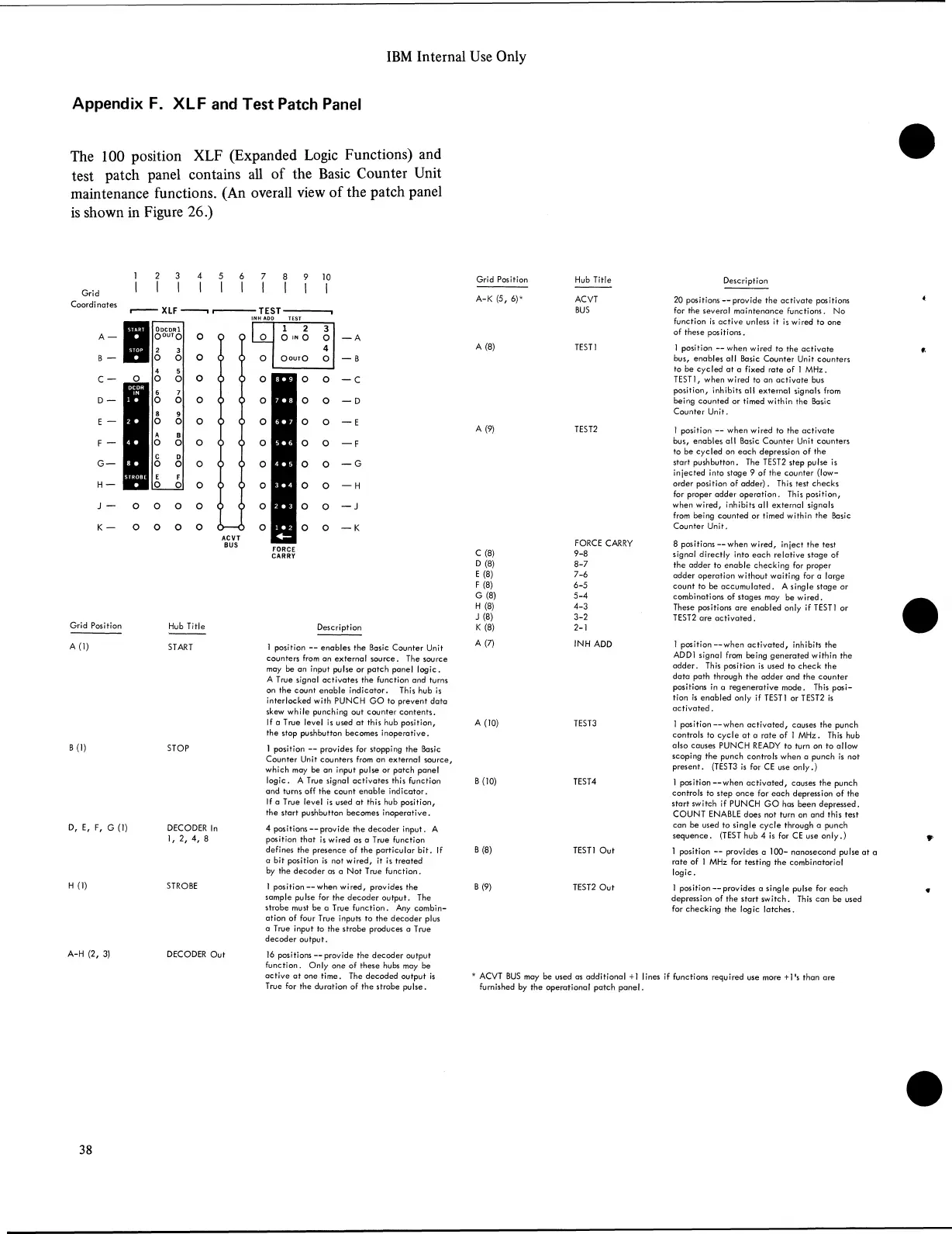
The 100 position XLF (Expanded Logic Functions) and
test patch panel contains all of the Basic Counter Unit
maintenance functions. (An overall view of the patch panel
is shown in Figure 26.)
Grid
Coordinates
A —
B —
C —
D —
E —
F —
G —
H —
J —
K —
— A
— B
— C
— D
— E
— F
— G
— H
— J
— K
Grid Position Hub Title
Description
A (1) START
B (1)
STOP
D, E, F, G (1) DECODER In
1, 2, 4, 8
H (1) STROBE
A-H (2, 3) DECODER Out
1 position — enables the Basic Counter Unit
counters from an external source. The source
may be an input pulse or patch panel logic.
A True signal activates the function and turns
on the count enable indicator. This hub is
interlocked with PUNCH GO to prevent data
skew while punching out counter contents.
If a True level is used at this hub position,
the stop pushbutton becomes inoperative.
1 position — provides for stopping the Basic
Counter Unit counters from an external source,
which may be an input pulse or patch panel
logic. A True signal activates this function
and turns off the count enable indicator.
If a True level is used at this hub position,
the start pushbutton becomes inoperative.
4 positions — provide the decoder input. A
position that is wired as a True function
defines the presence of the particular bit. If
a bit position is not wired, it is treated
by the decoder as a Not True function.
1 position — when wired, provides the
sample pulse for the decoder output. The
strobe must be a True function. Any combin
ation of four True inputs to the decoder plus
a True input to the strobe produces a True
decoder output.
16 positions — provide the decoder output
function. Only one of these hubs may be
active at one time. The decoded output is
True for the duration of the strobe pulse.
Grid Position
Hub Title
Description
A-K (5, 6)*
ACVT
BUS
20 positions — provide the activate positions
for the several maintenance functions. No
function is active unless it is wired to one
of these positions.
A (8)
TEST1
1 position — when wired to the activate
bus, enables all Basic Counter Unit counters
to be cycled at a fixed rate of 1 MHz.
TEST1, when wired to an activate bus
position, inhibits all external signals from
being counted or timed within the Basic
Counter Unit.
A (9)
TEST2
1 position — when wired to the activate
bus, enables all Basic Counter Unit counters
to be cycled on each depression of the
start pushbutton. The TEST2 step pulse is
injected into stage 9 of the counter (low-
order position of adder). This test checks
for proper adder operation. This position,
when wired, inhibits all external signals
from being counted or timed within the Basic
Counter Unit,
C (8)
D(8)
E (8)
F (8)
G (8)
H (8)
J (8)
K(8)
FORCE CARRY
9-8
8-7
7-6
6-5
5-4
4-3
3-2
2-1
8 positions — when wired, inject the test
signal directly into each relative stage of
the adder to enable checking for proper
adder operation without waiting for a large
count to be accumulated. A single stage or
combinations of stages may be wired.
These positions are enabled only if TEST1 or
TEST2 are activated.
A (7)
INH ADD
1 position— when activated, inhibits the
ADD1 signal from being generated within the
adder. This position is used to check the
data path through the adder and the counter
positions in a regenerative mode. This posi
tion is enabled only if TEST1 or TEST2 is
activated.
A (10)
TEST3
1 position— when activated, causes the punch
controls to cycle at a rate of 1 MHz. This hub
also causes PUNCH READY to turn on to allow
scoping the punch controls when a punch is not
present. (TEST3 is for CE use only.)
B (10)
TEST4
1 position— when activated, causes the punch
controls to step once for each depression of the
start switch if PUNCH GO has been depressed.
COUNT ENABLE does not turn on and this test
can be used to single cycle through a punch
sequence. (TEST hub 4 is for CE use only.)
B (8) TEST1 Out
1 position — provides a 100- nanosecond pulse at
rate of 1 MHz for testing the combinatorial
logic.
B (9) TEST2 Out
1 position — provides a single pulse for each
depression of the start switch. This can be used
for checking the logic latches.
* ACVT BUS may be used as additional +1 lines if functions required use more + ]'s than are
furnished by the operational patch panel.
38