IBM Internal Use Only
location (probe point) on the back panel of the equipment
being monitored. A probe point location may be minus (-)
or plus (+) as specified by the line name in the ALD pages.
A monitor probe connected to a minus (-) probe point
location detects either a minus (-) signal level or a plus (+)
signal level. Similarly, a monitor probe connected to a (+)
probe point detects either a minus (-) signal level or a
plus (+) signal level. Circuit conventions used within the
Basic Counter Unit define a signal to be true (active) at the
patch panel signal hub when the monitor probe detects a
minus (-) signal level at either a minus (-) or plus (+) probe
point location. A signal is not true (inactive, false) at the
patch panel signal hub when the monitor probe detects a
plus (+) signal level at either a minus (-) or plus (+) probe
point location.
Signal Polarity
at Probe Point
Location
minus (-) probe
point location
plus (+) probe
point location
Monitor Probe Signal
Level Detection
minus (-) signal level
plus (+) signal level
minus (-) signal level
plus (+) signal level
Patch Panel Logic
at Signal Hub
true (active)
not true (inactive,
false)
true (active)
not true (inactive,
false)
When connecting a monitor probe to a plus (+) probe
point location it may be necessary to invert the signal at the
signal hub on the patch panel to yield a true state.
Inversions of a signal at the signal hub is accomplished by
connecting the signal hub with a patch panel wire to the
input hub of any NOT function on the patch panel.
Logic Sections
Operational patch panel 1 and operational patch panel 2
provide the following logical functions:
Six AND functions
Four OR functions
Eight NOT functions
Four LATCH functions
Two OR LATCH functions
Four FANOUT functions
Eight Self-Generated True Sources
Operational patch panel 1 and operational patch panel 2
also provide additional logical functions that are derivatives
from some of the previously named logical functions:
Using the LATCH as a FANOUT
DOT OR functions
Using Inverted Logic
The XLF (expanded logic function) patch panel provides
the following logical functions:
One START/STOP function
One 4 x 16 Decoder function
The test patch panel provides 20 additional TRUE
functions. Other functions on the test patch panel are for
maintenance and test use only and are fully described in
“Appendix F.”
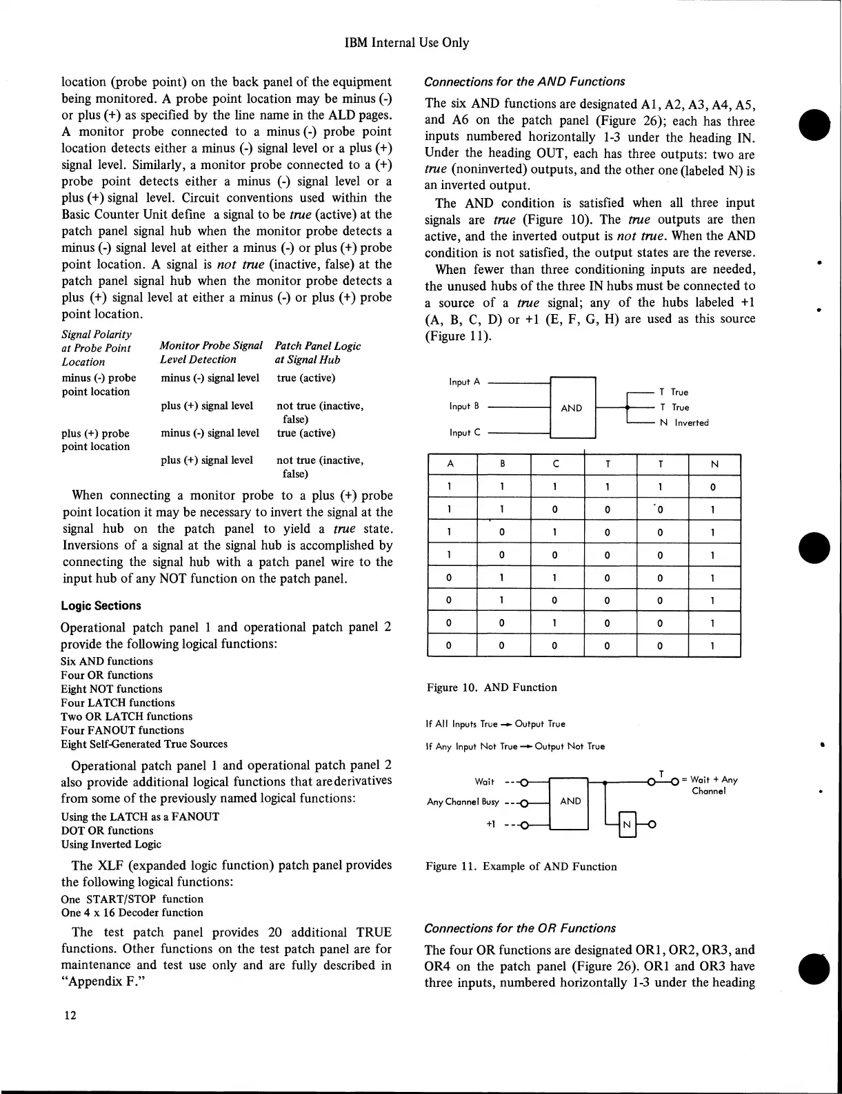
Connections for the AND Functions
The six AND functions are designated A l, A2, A3, A4, A5,
and A6 on the patch panel (Figure 26); each has three
inputs numbered horizontally 1-3 under the heading IN.
Under the heading OUT, each has three outputs: two are
true (noninverted) outputs, and the other one (labeled N) is
an inverted output.
The AND condition is satisfied when all three input
signals are true (Figure 10). The true outputs are then
active, and the inverted output is not true. When the AND
condition is not satisfied, the output states are the reverse.
When fewer than three conditioning inputs are needed,
the unused hubs of the three IN hubs must be connected to
a source of a true signal; any of the hubs labeled +1
(A, B, C, D) or +1 (E, F, G, H) are used as this source
(Figure 11).
Input A
Input B
Input C
T True
T True
N Inverted
A
B
c
T T
N
1 1
1
1 1
0
1 1
0
0
'0
1
1
0
1
0 0 1
1
0
0
0 0 1
0 1
1
0
0 1
0
1
0
0 0
1
0
0 1
0 0 1
0
0
0
0 0
1
Figure 10. AND Function
If All Inputs True -► Output True
If Any Input Not True—►Output Not True
Wait
Any Channel Busy
+1
0 ^ - 0 = Wait + Any
Channel
N
Figure 11. Example of AND Function
Connections for the OR Functions
The four OR functions are designated 0R 1,0R 2, 0R3, and
0R4 on the patch panel (Figure 26). 0R1 and 0R3 have
three inputs, numbered horizontally 1-3 under the heading
12