IBM Internal Use Only
IN. Under the heading OUT, each has two true outputs.
OR1 and OR3 can serve as either an OR function or as a
LATCH function. See “Connections for the OR LATCH
Functions.”
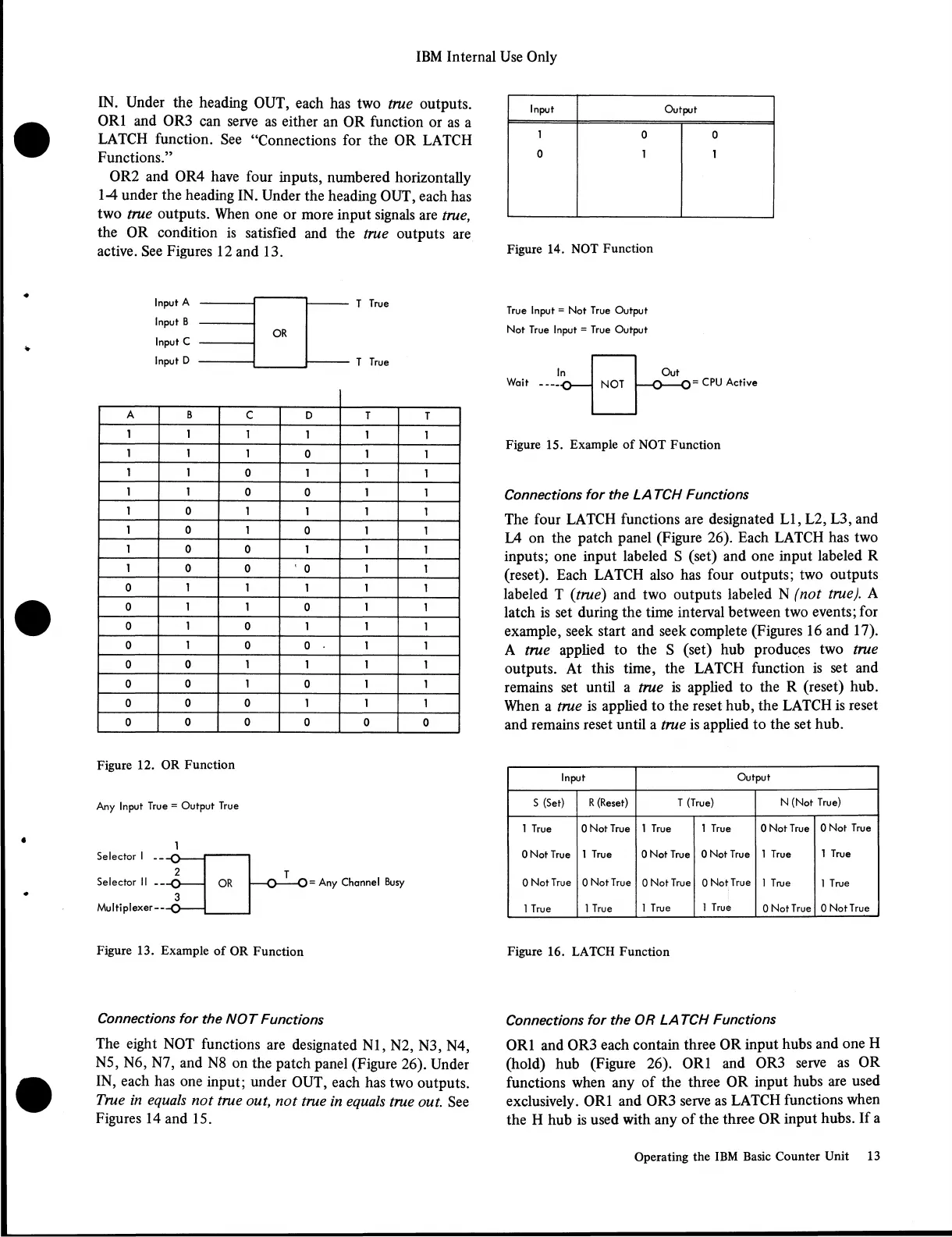
OR2 and OR4 have four inputs, numbered horizontally
1-4 under the heading IN. Under the heading OUT, each has
two true outputs. When one or more input signals are true,
the OR condition is satisfied and the true outputs are
active. See Figures 12 and 13.
Input Output
1
0
0
1
0
1
Figure 14. NOT Function
Input A
Input B
Input C
Input D
OR
T True
T True
A
B
c
D
T
T
1 1
1
1
1 1
1 1
1
0
1
1
1 1
0 1
1
1
1 1
0
0 1
1
1
0
1
1 1
1
1 0
1
0 1 1
1 0
0 1 1
1
1
0
0
’ 0 1 1
0 1 1
1 1 1
0
1
1
0
1
1
0
1
0 1 1
1
0
1
0
0 .
1 1
0 0 1 1 1
1
0
0 1
0 1 1
0 0
0
1 1
1
0
0 0
0
0
0
Figure 12. OR Function
Any Input True = Output True
1
Selector I
Selector II --
Multiplexer—
= Any Channel Busy
True Input = Not True Output
Not True Input = True Output
Wait = CPU Active
Figure 15. Example of NOT Function
Connections for the LA TCH Functions
The four LATCH functions are designated LI, L2, L3, and
L4 on the patch panel (Figure 26). Each LATCH has two
inputs; one input labeled S (set) and one input labeled R
(reset). Each LATCH also has four outputs; two outputs
labeled T (true) and two outputs labeled N (not true). A
latch is set during the time interval between two events; for
example, seek start and seek complete (Figures 16 and 17).
A true applied to the S (set) hub produces two true
outputs. At this time, the LATCH function is set and
remains set until a true is applied to the R (reset) hub.
When a true is applied to the reset hub, the LATCH is reset
and remains reset until a true is applied to the set hub.
Input
Output
s (Set)
R (Reset) T (True)
N (Not True)
1 True
0 Not True 1 True 1 True
0 Not True
0 Not True
0 Not True
1 True
0 Not True
0 Not True
1 True
1 True
0 Not True 0 Not True
0 Not True
0 Not True
1 True
1 True
1 True
1 True
1 True
1 True
0 Not True
0 Not True
Figure 13. Example of OR Function
Figure 16. LATCH Function
Connections for the NOT Functions
The eight NOT functions are designated N l, N2, N3, N4,
N5, N6, N7, and N8 on the patch panel (Figure 26). Under
IN, each has one input; under OUT, each has two outputs.
True in equals not true out, not true in equals true out. See
Figures 14 and 15.
Connections for the OR LA TCH Functions
OR1 and OR3 each contain three OR input hubs and one H
(hold) hub (Figure 26). OR1 and OR3 serve as OR
functions when any of the three OR input hubs are used
exclusively. OR1 and OR3 serve as LATCH functions when
the H hub is used with any of the three OR input hubs. If a
Operating the IBM Basic Counter Unit 13