IBM Internal Use Only
Set = True until Reset
Reset = Not True until Set
Seek Start _ _
Seek Complete - -
Seek Time
S =
'0
LATCH is Set at to and Reset at t2
Figure 17. Example of LATCH Function
true is first applied to an H hub and if a true is applied to
any of the three OR input hubs, a LATCH is set and
remains set until reset by a not true at the H hub. Think of
the H hub as a hold hub, holding a true signal; the hold is
removed when the signal changes from true to not true
(Figure 18).
Seek
Complete
Not Seek
Seek
Time
Figure 18. Example of OR LATCH Function
Connections for the FANOUT Functions
The four FANOUT functions are designated F1,F2,
F3, and F4 on the patch panel (Figure 26). Each FANOUT
has one input labeled IN and two outputs labeled OUT.
Think of the FANOUT function as a duplicating function:
any true input is duplicated twice as true output and any
not true input is duplicated twice as not true output
(Figure 19).
Seif-Generated True Signals
Four sources of self-generated true signals are designated +1
(A, B, C, D) on operational patch panel 1, and four sources
of self-generated true signals are designated +1 (E, F, G, H)
on operational patch panel 2 (Figure 26). These eight
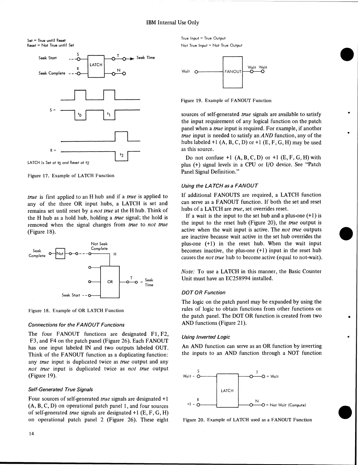
True Input = True Output
Not True Input = Not True Output
Wait O -
Wait Wait
Figure 19. Example of FANOUT Function
sources of self-generated true signals are available to satisfy
the input requirement of any logical function on the patch
panel when a true input is required. For example, if another
true input is needed to satisfy an AND function, any of the
hubs labeled +1 (A, B, C, D) or +1 (E, F, G, H) may be used
as this source.
Do not confuse +1 (A, B, C, D) or +1 (E, F, G, H) with
plus (+) signal levels in a CPU or I/O device. See “Patch
Panel Signal Definition.”
Using the LA TCH as a FANOUT
If additional FANOUTS are required, a LATCH function
can serve as a FANOUT function. If both the set and reset
hubs of a LATCH are true, set overrides reset.
If a wait is the input to the set hub and a plus-one (+1) is
the input to the reset hub (Figure 20), the true output is
active when the wait input is active. The not true outputs
are inactive because wait active in the set hub overrides the
plus-one (+1) in the reset hub. When the wait input
becomes inactive, the plus-one (+1) input in the reset hub
causes the not true hub to become active (equal to not-wait).
Note: To use a LATCH in this manner, the Basic Counter
Unit must have an EC258994 installed.
DOT OR Function
The logic on the patch panel may be expanded by using the
rules of logic to obtain functions from other functions on
the patch panel. The DOT OR function is created from two
AND functions (Figure 21).
Using Inverted Logic
An AND function can serve as an OR function by inverting
the inputs to an AND function through a NOT function
s
Wait - o-
R
+i - a
LATCH
T
■O
------
O = Wait
= Not Wait (Compute)
Figure 20. Example of LATCH used as a FANOUT Function
14