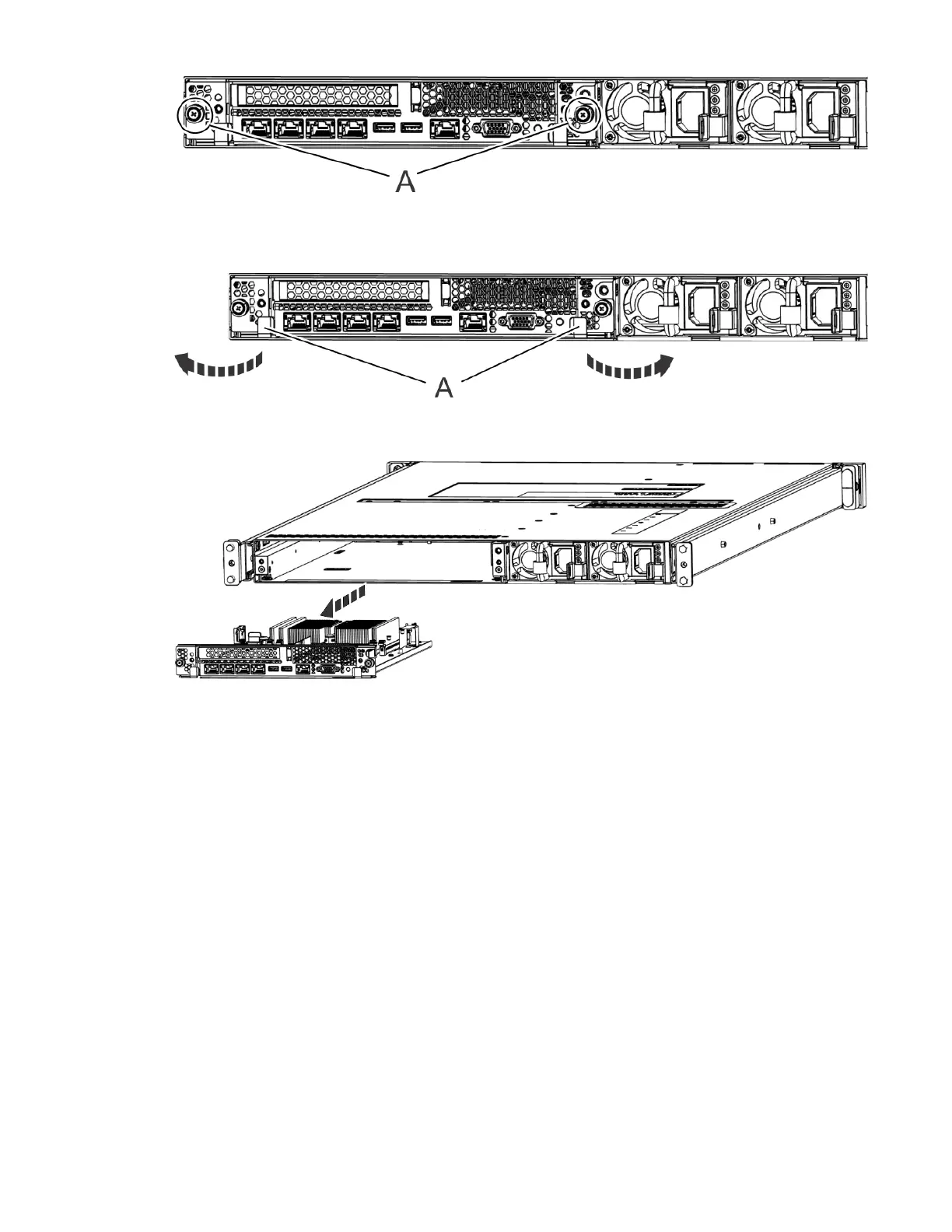
Figure 114. Removing the system backplane screws
d) Simultaneously rotate the two levers (A) on each side of the system backplane out and to the side
to unlock the system backplane from the system.
Figure 115. Unlatching the system backplane
e) Support the system backplane by the bottom as you slide it from the system.
Figure 116. Removing the system backplane
f) Place the system backplane on an ESD surface.
Note: You must remove and replace the system backplane at a flat angle. The ventilation holes in
the top cover can come into contact with the DIMMs in the system backplane if the insertion of the
backplane is at an angle or is rushed. As a result of possible contact, DIMMs can be scratched and can
leave residue on the top cover.
3. Pull small the lever (A) slightly away from the trusted platform module to release the module and lift
the module straight up from its slot on the system backplane.
90
Power Systems: Servicing the IBM Power Systems HMC (7063-CR2)

 Loading...


