9. If you are installing new hardware in a logical partition, you need to understand and plan for the
implications of partitioning your system. For information, see Logical Partitioning.
Identifying the 7063-CR2 system that contains the part to replace
Learn how to determine which system has the part you want to replace.
LEDs on the 7063-CR2 system
Use this information as a guide to the LEDs on the IBM Power Systems HMC (7063-CR2) system.
The LEDs indicate various system statuses. If the part does not have a problem indicator LED, you can use
a troubleshooting program such as impitool to identify the issue.
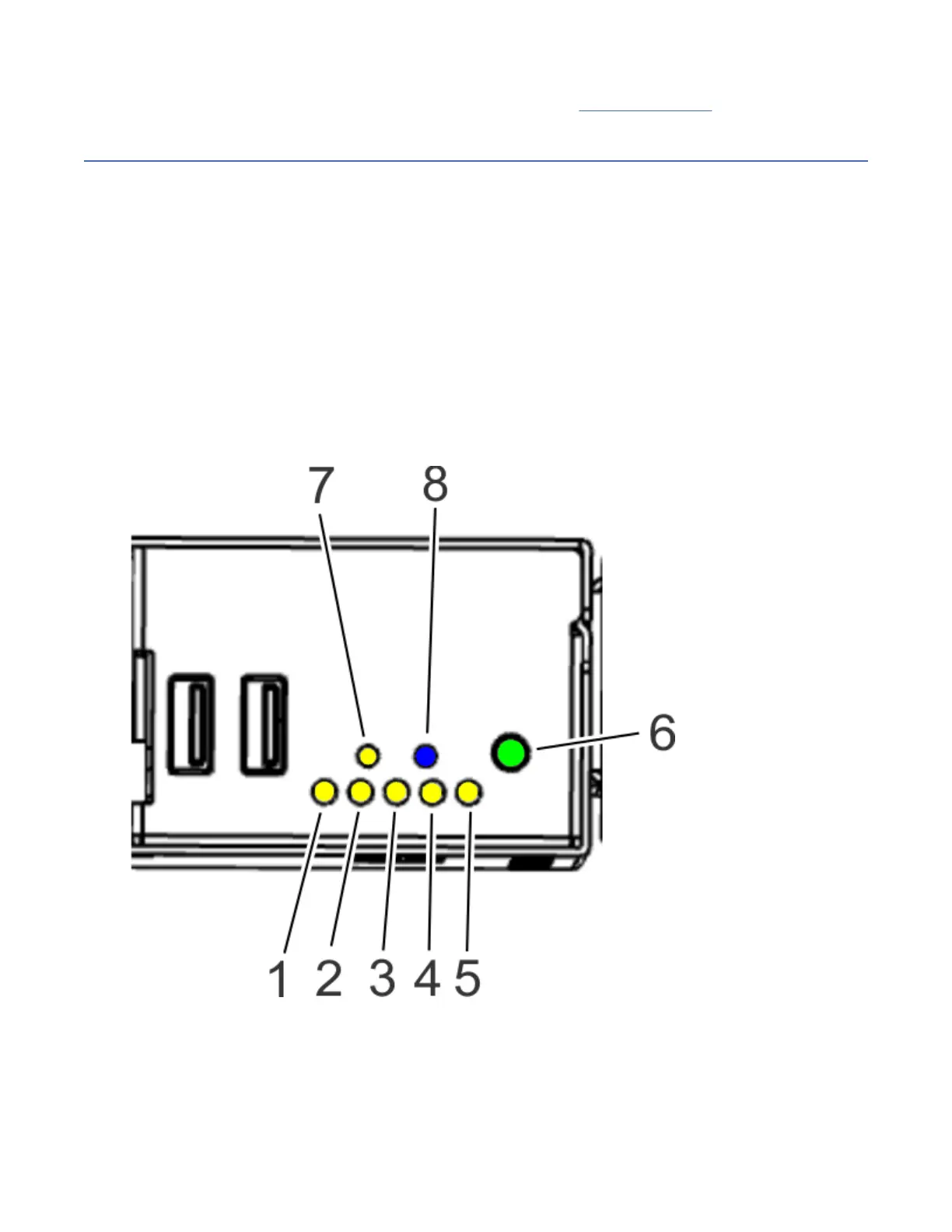
The front control panel LEDs are shown in the following gure.
• The green LED (6) indicates the power status (on or off). The LED flashes when the BMC is at standby.
The LED is solid when the system is running.
• The blue identify LED (8) identies the system to be serviced.
• The amber LED (7) indicates a system fault.
• The fan LEDs (1) - (5) indicate an issue with the corresponding fan.
Figure 119. Control panel LEDs
The drive LEDs are shown in the following gure.
• The green LED indicates the power status (on or off).
• The amber LED flashes when there is activity.
96
Power Systems: Servicing the IBM Power Systems HMC (7063-CR2)

 Loading...


