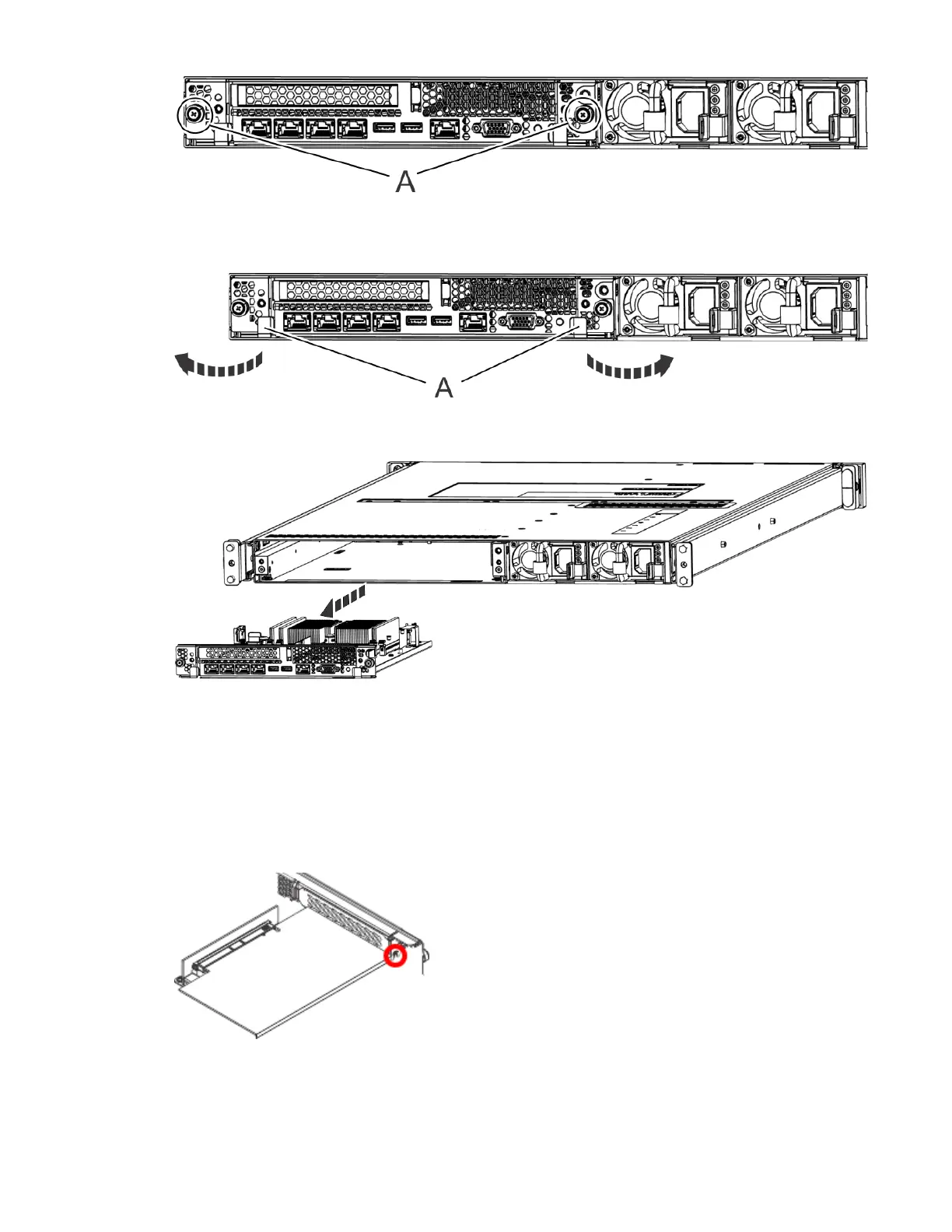
Figure 36. Removing the system backplane screws
d) Simultaneously rotate the two levers (A) on each side of the system backplane out and to the side
to unlock the system backplane from the system.
Figure 37. Unlatching the system backplane
e) Support the system backplane by the bottom as you slide it from the system.
Figure 38. Removing the system backplane
f) Place the system backplane on an ESD surface.
Note: You must remove and replace the system backplane at a flat angle. The ventilation holes in
the top cover can come into contact with the DIMMs in the system backplane if the insertion of the
backplane is at an angle or is rushed. As a result of possible contact, DIMMs can be scratched and can
leave residue on the top cover.
4. Remove the PCIe adapter from the PCIe riser.
a) Remove the screw that secures the PCIe adapter to the system backplane.
Figure 39. Removing the tail-stock screw
b) Open the retainer clip that secures the PCIe adapter to the PCIe riser, by moving the blue lever to
the unlocked position.
34
Power Systems: Servicing the IBM Power Systems HMC (7063-CR2)

 Loading...


