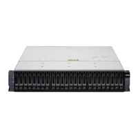
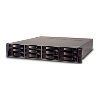
I/O enclosures
The I/O enclosure provides connectivity between the adapters and the processor node.
The I/O enclosure uses PCIe interfaces to connect I/O adapters in the I/O enclosure to both processor
nodes. A PCIe device is an I/O adapter or a processor node.
To improve I/O operations per second (IOPS) and sequential read/write throughput, the I/O enclosure is
connected to each processor node with a point-to-point connection.
The I/O enclosure contain the following adapters:
Flash interface connectors
Interface connector that provides PCIe cable connection from the I/O enclosure to the High
Performance Flash Enclosure Gen2.
Host adapters
An I/O enclosure can support up to 16 host ports.
Each of the four 16 or 32 Gbps Fibre Channel ports on a PCIe-attached host adapter can be
independently congured to use SCSI/FCP or FICON/zHPF protocols. Both longwave and shortwave
adapter versions that support different maximum cable lengths are available. The host-adapter ports
can be directly connected to attached hosts systems or storage systems, or connected to a storage
area network. SCSI/FCP ports are used for connections between storage systems. SCSI/FCP ports
that are attached to a SAN can be used for both host and storage system connections.
The High Performance FICON Extension (zHPF) protocol can be used by FICON host channels that
have zHPF support. The use of zHPF protocols provides a signicant reduction in channel usage. This
reduction improves I/O input on a single channel and reduces the number of FICON channels that are
required to support the workload.
Processor nodes
The processor nodes drive all functions in the storage system. Each node consists of a Power server that
contains POWER9 processors and memory.
Management enclosure
The management enclosure houses the HMCs and the switch and power components that support them.
The management enclosure contains the following components:
• Two Hardware Management Consoles (HMCs)
• Two Ethernet switches
• Two power control cards
• Two power supply units (PSUs) to power the management enclosure
• One Local/Remote switch assembly
Management console
The management console is also referred to as the Hardware Management Console (or HMC). It supports
storage system hardware and rmware installation and maintenance activities.
The HMC connects to the customer network and provides access to functions that can be used to manage
the storage system. Management functions include logical conguration, problem notication, call home
for service, remote service, and Copy Services management. You can perform management functions
from the DS8000 Storage Management GUI, DS command-line interface (DS CLI), or other storage
management software that supports the storage system.
8
IBM DS8900F: DS8900F Introduction and Planning Guide
 Loading...
