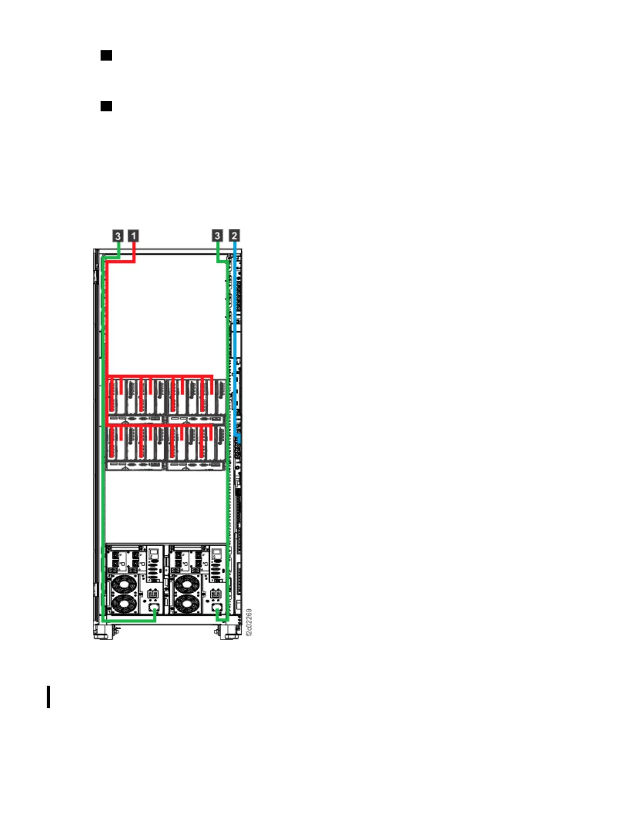
2 Network Ethernet cable, power sequence cables, and customer analog phone line (if used). The
network Ethernet cable, in blue, is routed from the top of the rack to the rear rack connector. The rack
connector has an internal cable to the management console. The power sequence cables and private
network Ethernet cables (one gray and one black) for a partner storage system are also located here.
3 Mainline power cords. Two top-exit mainline power cords for each rack, which are shown in green,
are routed here.
Notes:
• A technical service representative tests the power sources. The customer is required to provide power
outlets (for connecting power cords) within the specied distance.
• Fibre Channel host cables are internally routed and connected by either the customer or by a technical
service representative.
• All remaining cables are internally routed and connected by a technical service representative.
Figure 7. Top exit feature installed (cable routing and top exit locations)
Feature codes for overhead cable management (top-exit bracket)
Use this feature code to order cable management for overhead cabling (top exit bracket) for your model
994, 996, or E96.
Note: In addition to the top-exit bracket, one ladder (feature code 1101) must also be purchased for a
site where the top-exit bracket for ber cable feature is used. The ladder is used to ensure safe access
when your storage system is serviced with a top-exit bracket feature installed.
Chapter 6. Delivery and installation requirements
85