Figure 40. CMA release buttons
3. Slide the inner CMA arm connector (A) onto the lower right inner rail connector (B) as shown in the
following gure.
Figure 41. Installing inner CMA arm connector on inner rail connector
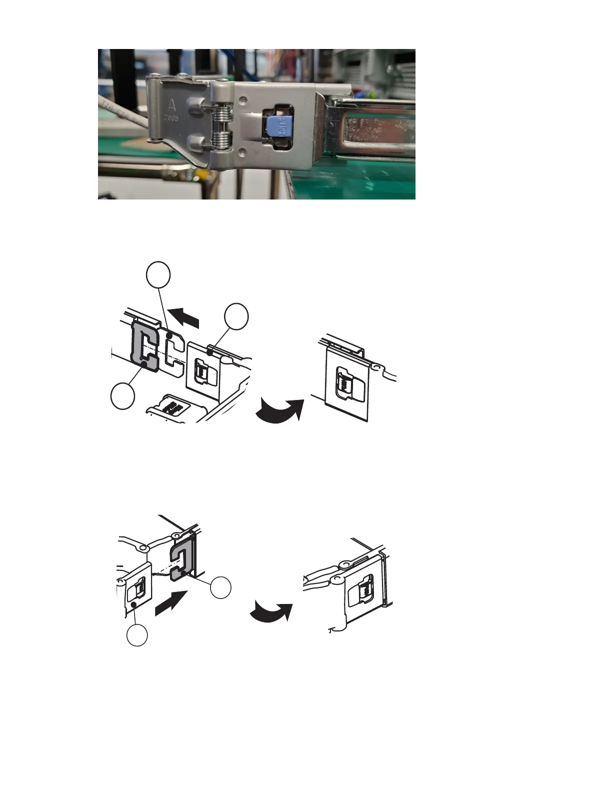
4. Slide the outer CMA arm connector (C) onto the lower right outer rail connector (D) as shown in the
following gure.
Figure 42. Installing outer CMA arm connector on outer rail connector
5. Slide the CMA body connector (E) onto the lower left CMA body rail (F) as shown in the following gure.
Chapter 4. Installing
57

 Loading...


