• If the rack cabinet you are relocating was supplied with removable outriggers they must be
reinstalled before the cabinet is relocated.
• Inspect the route that you plan to take to eliminate potential hazards.
• Verify that the route that you choose can support the weight of the loaded rack cabinet. Refer to
the documentation that comes with your rack cabinet for the weight of a loaded rack cabinet.
• Verify that all door openings are at least 760 x 230 mm (30 x 80 in.).
• Ensure that all devices, shelves, drawers, doors, and cables are secure.
• Ensure that the four leveling pads are raised to their highest position.
• Ensure that there is no stabilizer bracket installed on the rack cabinet during movement.
• Do not use a ramp inclined at more than 10 degrees.
• When the rack cabinet is in the new location, complete the following steps:
– Lower the four leveling pads.
– Install stabilizer brackets on the rack cabinet.
– If you removed any devices from the rack cabinet, repopulate the rack cabinet from the
lowest position to the highest position.
• If a long-distance relocation is required, restore the rack cabinet to the conguration of the rack
cabinet as you received it. Pack the rack cabinet in the original packaging material, or equivalent.
Also lower the leveling pads to raise the casters off the pallet and bolt the rack cabinet to the
pallet. (R002)
DANGER:
Racks with a total weight of > 227 kg (500 lb.), Use Only Professional Movers! (R003)
DANGER: Do not transport the rack via fork truck unless it is properly packaged, secured on top of
the supplied pallet. (R004)
DANGER:
Main Protective Earth (Ground):
This symbol is marked on the frame of the rack.
The PROTECTIVE EARTHING CONDUCTORS should be terminated at that point. A recognized or
certied closed loop connector (ring terminal) should be used and secured to the frame with a lock
washer using a bolt or stud. The connector should be properly sized to be suitable for the bolt or
stud, the locking washer, the rating for the conducting wire used, and the considered rating of the
breaker. The intent is to ensure the frame is electrically bonded to the PROTECTIVE EARTHING
CONDUCTORS. The hole that the bolt or stud goes into where the terminal conductor and the lock
washer contact should be free of any non-conductive material to allow for metal to metal contact.
All PROTECTIVE EARTHING CONDUCTORS should terminate at this main protective earthing
terminal or at points marked with . (R010)
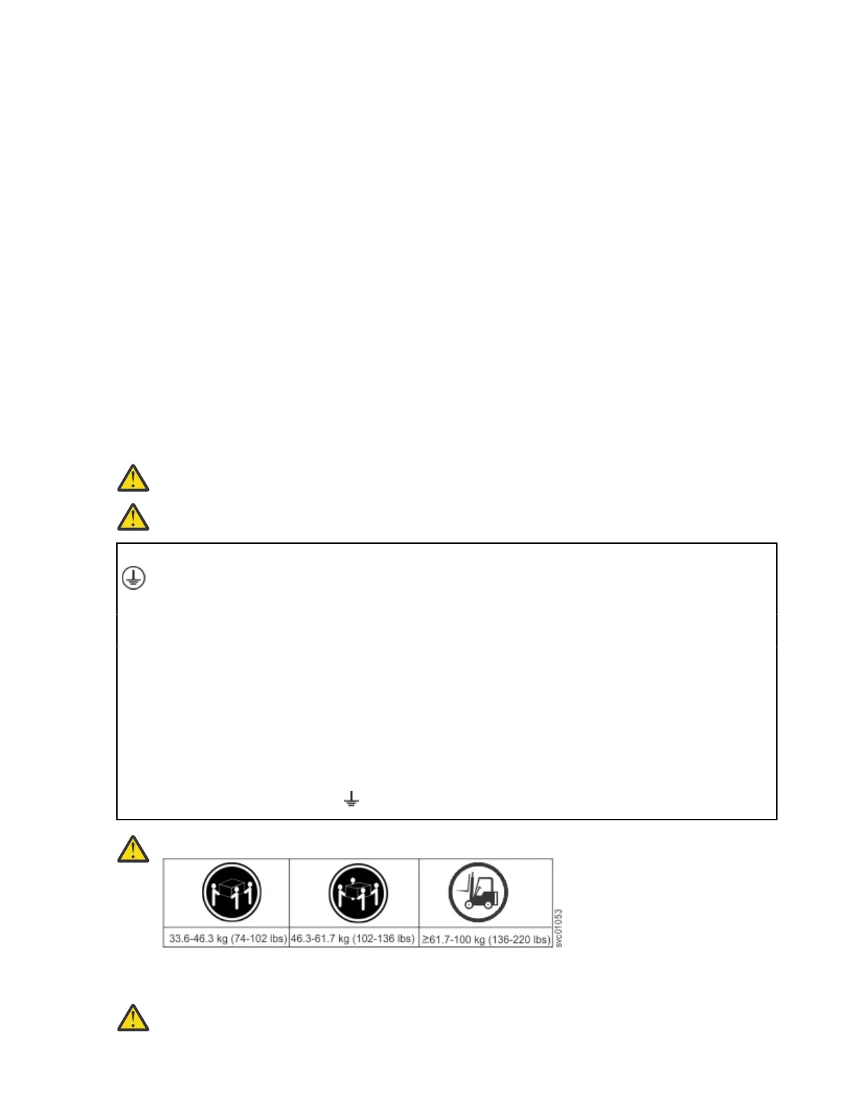
CAUTION:
The weight of this part or unit is more than 55 kg (121.2 lb). It takes specially trained persons, a
lifting device, or both to safely lift this part or unit. (C011)
CAUTION: To avoid personal injury, before lifting this unit, remove all appropriate subassemblies
per instructions to reduce the system weight. (C012)
Chapter 4. Installing the system hardware 29