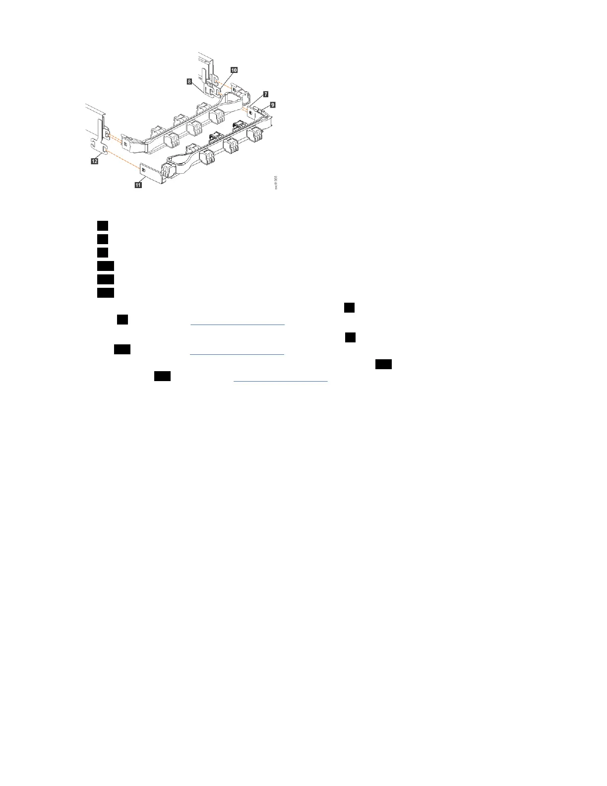
Figure 46. Comparing the location of the components of the CMA assemblies
7 Inner connector on lower CMA
8 Connector base on inner rail member
9 Outer connector on lower CMA
10 Connector base on outer rail member
11 Support rail connector the lower CMA
12 Connector base on outer rail member
5. Install the inner connector of the lower CMA assembly ( 7 ) to the inner member of the right support
rail ( 8 ), as shown in Figure 46 on page 51).
6. Install the outer connector of the lower CMA assembly ( 9 ) to the outer member of the right support
rail 10 , as shown in Figure 46 on page 51.
7. Attach the support rail connector on the lower CMA assembly ( 11 ) to the connector on the left
support rail ( 12 ), as shown in Figure 46 on page 51.
Ensure that the lower CMA assembly is securely attached to the hooks on the end of the support rails.
8. Route the cables and power cords on the CMA. If needed, secure them with cable ties or hook-and-
loop fasteners.
Notes:
• Use the cable straps that are provided on the rear of the system to retain the cables and prevent
them from sagging.
• Allow slack in all of the cables to avoid tension in the cables as the CMA moves.
9. Reconnect the power cords and other cables, as needed.
Removing and installing a SAS cable
Use the following procedures to attach SAS cables to the 5U enclosure during the initial installation
process. You can also remove a faulty SAS cable and replace it with a new one received from FRU stock.
About this task
Be careful when you are replacing the hardware components that are located in the back of the system.
Do not inadvertently disturb or remove any cables that you are not instructed to remove.
If you replace more than one cable, record which two ports, canisters, and enclosures each cable
connects, so you can match the connections with the replacement cables. The system cannot operate if
the SAS cabling to the expansion enclosure is incorrect.
When the 5U expansion enclosure is installed in the rack, the expansion canisters are upside down. The
input cable connects to the right port (port 1) on the expansion canister. The output cable connects to the
left port (port 2) on the canister.
Chapter 4. Installing the system hardware
51
 Loading...