Installing or replacing the cable-management arm
Use these procedures to install the cable-management arm (CMA) for the 5U expansion enclosure. You
can also use these procedures to replace a faulty CMA assembly.
About this task
As part of the initial installation of the 5U expansion enclosure, you must attach the CMA. You might also
need to replace a faulty CMA with a new one from FRU stock.
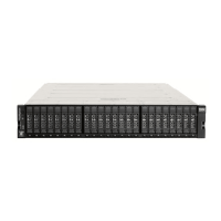
The cable management arm (CMA) consists of an upper arm and a lower arm assembly, as Figure 40 on
page 49 shows.
Figure 40. Upper and lower cable-management arms
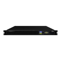
As Figure 41 on page 49 shows, the support rail connectors of each CMA assembly are installed on the
rail hooks at the end of the support rails.
Figure 41. Upper and lower cable-management arms
Procedure
1. Remove the loop straps from the upper and lower CMA assemblies. The straps are used only for
shipping.
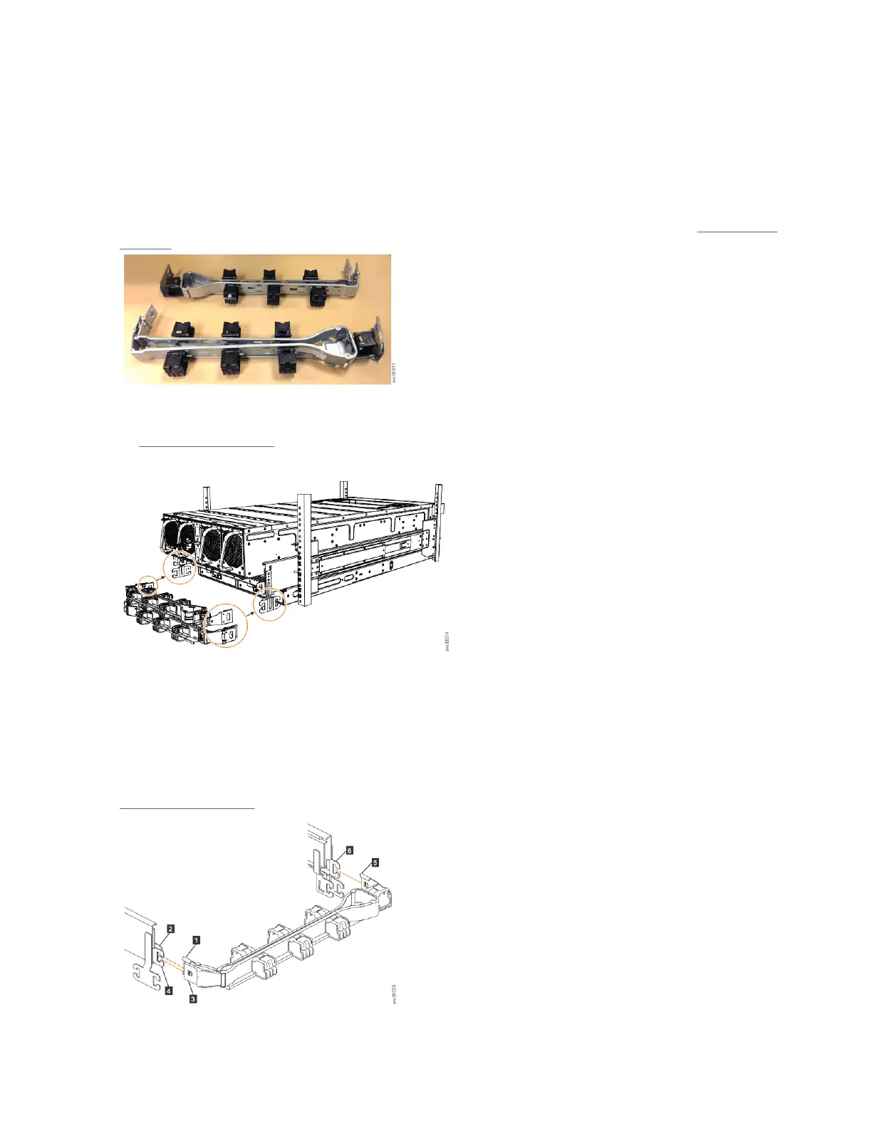
Installing the upper CMA assembly
Figure 42 on page 49 shows the connectors on the upper CMA assembly.
Figure 42. Connectors for the cable management arm
Chapter 4. Installing the system hardware
49