Powering on the system
After you install all hardware components, you must power on the system and check its status.
About this task
Attention: Do not power on the system with any open bays or slots. Open bays or slots disrupt the
internal air flow, causing the drives to receive insufcient cooling.
• Every unused drive bay must be occupied by a ller panel.
• Filler panels must be installed in all empty host interface adapter slots.
Note: The AC power supply unit, and the DC power supply unit in DC-powered models, features a cable
retainer to secure the power cable.
Use the cable retainers to secure the power cables from being accidentally pulled out of the enclosure.
The cable retainer, which is on the back of each PSU handle, has a curved opening that faces the rear of
the PSU. After you plug the power cables in to the PSU, slip the power cable behind the retainer. Then,
pull the cable back into the retainer opening to secure the cable.
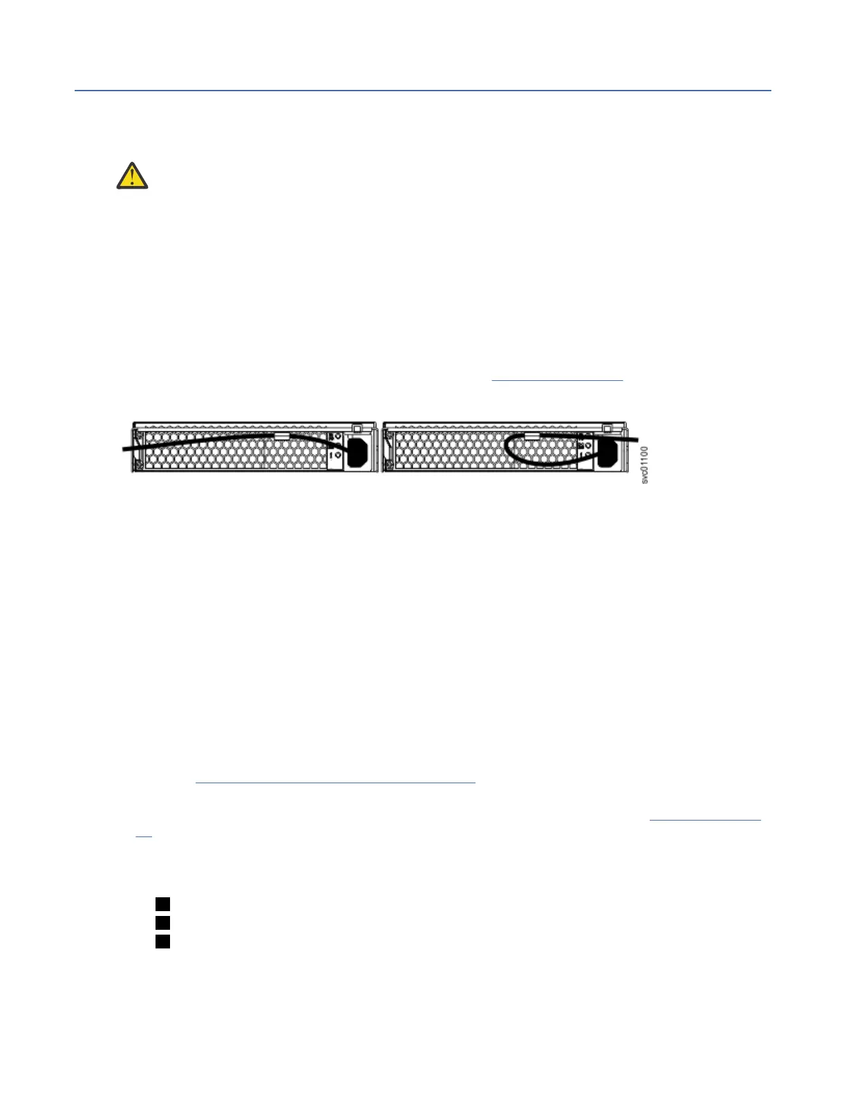
Each cable must be routed through the retainer, as shown in Figure 67 on page 68. For PSU 1, hook the
power cable underneath the cable retainer so the cable can extend to the left. For PSU 2, make a loop to
secure the cable under the retainer and extend the power cable to the right side of the enclosure.
Figure 67. Routing the power cables through the cable retainer
To remove the power cable, push the cable forward to unhook it from the cable retainer. Then, unplug the
cable from the PSU.
Procedure
To power on the system, complete the following steps.
1. Power on the control enclosure. Use the supplied power cords to connect both power supply units of
the enclosure to their power sources.
If the power sources have circuit breakers or switches, ensure that they are turned on. The enclosure
does not have power switches.
Notes:
• Each enclosure has two power supply units. To provide power failure redundancy, connect the two
power cords to separate power circuits.
• Review the information on securing the power cables to ensure that each power cable is secured to
each PSU on the back of the enclosure.
2. From the rear of the control enclosure, check the LEDs on each node canister. (See Figure 68 on page
68.)
Figure 68. Node canister LEDs
1 Power
2 Status
3 Fault
The canister is ready with no critical errors when Power is illuminated, Status is flashing, and Fault is
off. If a canister is not ready, refer to the "Procedure: Understanding the system status using the LEDs"
topic in "Troubleshooting".
68
IBM FlashSystem 5000 : FlashSystem 5000 Quick Installation Guide