8. Attach the remaining sections of the support rails to the rack, as described in step “6” on page 41 in
“Installing the support rails ” on page 40.
9. Move the mechanical lift to the front of the rack. Align the inner section of the rails with the mid
section of the rails that are extending from the rack.
10. On each side, push the inner section and middle section of the rails together until they click and will
no longer separate, as described in step “1” on page 48 in “Installing or replacing a 5U expansion
enclosure in a rack ” on page 47.
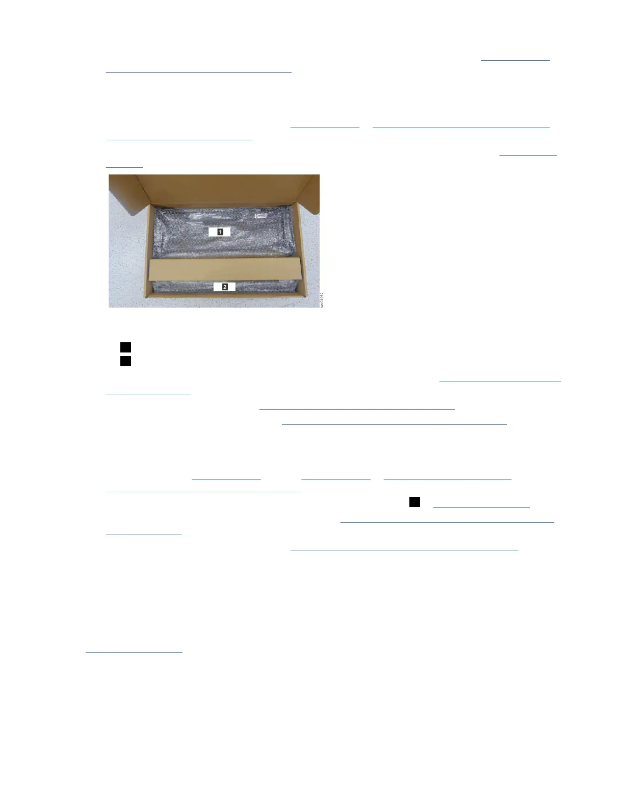
11. Remove the 4U and 1U fascia from the boxes in which they were shipped, as shown in Figure 14 on
page 37.
Figure 14. Packaging for fascia
1 4U fascia (front)
2 1U fascia (power supply units)
12. Attach the 4U and 1U fascia to the front of the enclosure, as described in “Installing or replacing the
fascia” on page 42.
13. Install the drives, as described in “Installing or replacing a drive” on page 44.
14. Replace the top cover, as described in “Installing or replacing the top cover” on page 46.
15. Lower the mechanical lift so that you can remove the remaining foam blocks away from the
expansion enclosure.
16. Slide the latch on the side of each rail and push the expansion enclosure securely into the rack, as
described in steps “4” on page 48 through “6” on page 48 in “Installing or replacing a 5U
expansion enclosure in a rack ” on page 47.
17. Remove the cable management arm assembly from its packaging ( 2 in Figure 12 on page 36).
18. Attach the cable management arm, as described in “Installing or replacing the cable-management
arm” on page 49.
19. Connect the SAS cables, as described in “Removing and installing a SAS cable” on page 51.
20. Connect the power cables.
Identify the hardware components
You should become familiar with the external components of the 5U expansion enclosure.
Components on the front of the enclosure
Figure 15 on page 38 shows the front of the 5U expansion enclosure. In the gure, all parts are installed
in the enclosure.
Chapter 4. Installing the system hardware
37