• When all components and drives are installed, the expansion enclosure is heavy. Install the support
rails and enclosure at the lowest available position. Do not install the rails and enclosure above
position U25 in the rack.
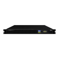
3. Remove the inner member of the rail. Push the tab ( a ) and slide the middle rail member back, as
shown in Figure 23 on page 41.
Figure 23. Detaching the inner rail section
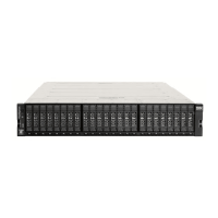
4. Use four M4 screws to attach the inner rail to the side of the enclosure. Figure 24 on page 41 shows
the screw locations.
Figure 24. Screw locations to attach the inner rail to the enclosure
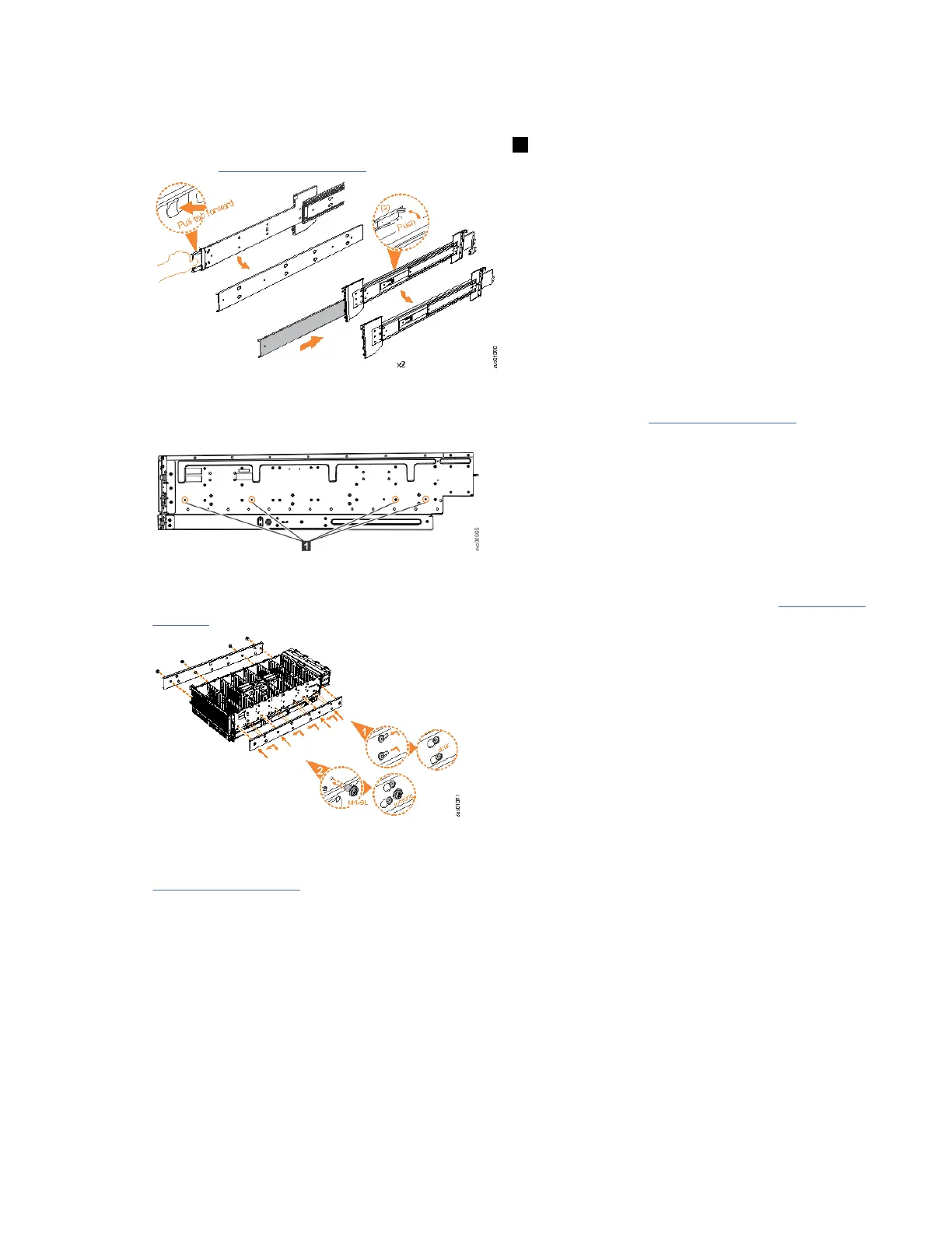
5. Install the inner section of the rail onto each side of the expansion enclosure, as shown in Figure 25 on
page 41.
Figure 25. Attaching the inner rail section to the enclosure
6. Use the M5 screws to install the outer rail member and bracket assembly to the rack, as shown in
Figure 26 on page 42.
Chapter 4. Installing the system hardware
41