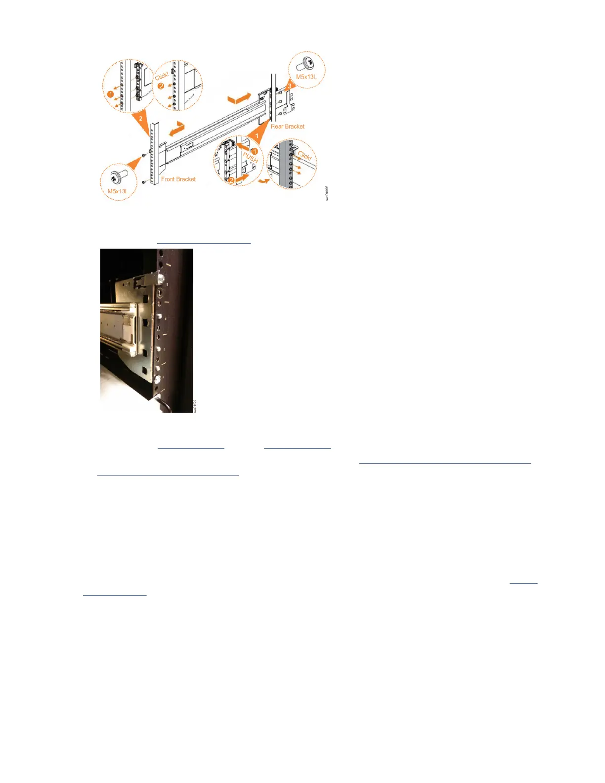
Figure 26. Installing the rail assembly to the rack frame
For example, Figure 27 on page 42 shows the front of the rail that is attached to the frame.
Figure 27. Example of the required rack space
7. Repeat steps “5” on page 41 through “6” on page 41 to install the opposite rail.
8. Install the expansion enclosure in the rack, as described in “Installing or replacing a 5U expansion
enclosure in a rack ” on page 47.
Installing or replacing the fascia
During the initial installation process or after you perform service, you can install the fascia components
on the front of a 5U expansion enclosure.
About this task
The 4U fascia covers the display panel of the expansion enclosure. It is attached to the enclosure by four
screws. The bottom 1U fascia covers both of the power supply units (PSUs) on the enclosure. As Figure
28 on page 43 shows, the fascias are independent; you can remove or replace one without having to
remove or replace the other.
42
IBM FlashSystem 5000 : FlashSystem 5000 Quick Installation Guide