Adapter-cassette retainer placement for short adapters
v Remove the adapter stabilizer (C). See Figure 68 on page 133.
v Place the hook arm (D) into the hole in the corner of the adapter. This supports the card
when it is undocked from the connector on the system backplane.
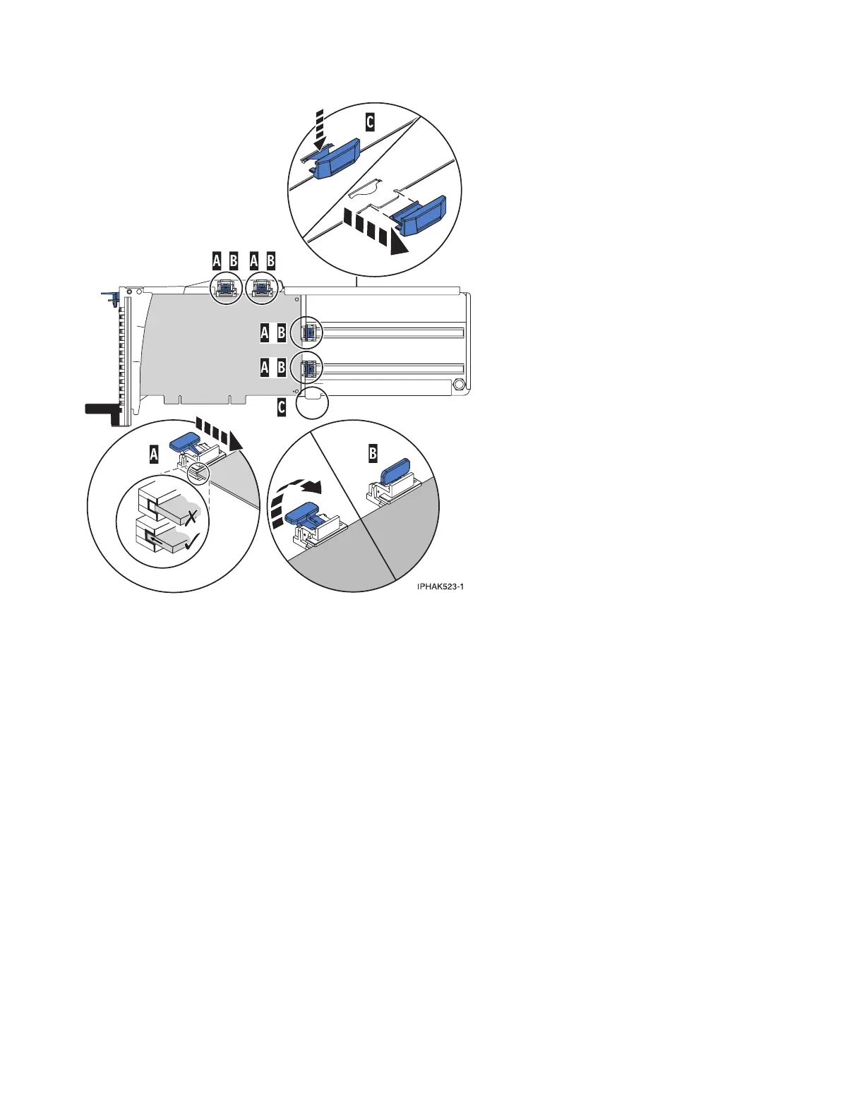
v Place and lock the retainers (B).
v Ensure the adapter edge is seated in each retainer groove (A). If the shape of the adapter or
the presence of a connector will not allow the adapter edge to be seated into the retainer
groove, ensure the retainer is still locked firmly against that edge or connector.
Figure 67. Medium-length adapter in the PCI adapter cassette with the supports in place
132
 Loading...


