9. Remove the drive signal and drive power cables from the system backplane. For instructions, see
“Removing the disk drive backplane from the 7063-CR1” on page 8.
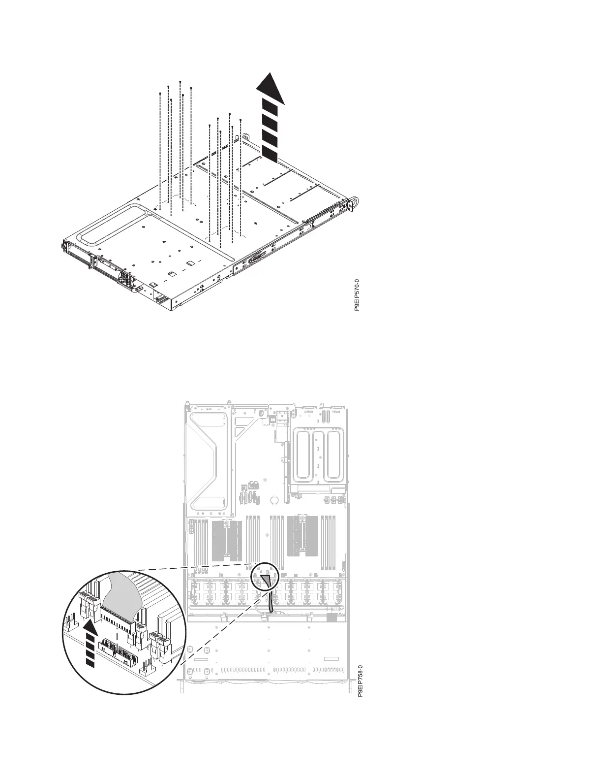
10. Remove the operator panel cable from the system backplane as shown in Figure 31.
Figure 30. Processor socket screws on the bottom of the chassis
Figure 31. Removing the operator panel cable
32 Power Systems: Servicing the 7063-CR1 Hardware Management Console system
 Loading...


