EasyManuals Logo

IBM Storwize V5000 Gen2 User Manual

IBM Storwize V5000 Gen2
204 pages
To Next Page IconTo Next Page
To Previous Page IconTo Previous Page
Page #86 background imageLoading...
Page #86 background image
To complete many service tasks, you can swing the CMA assemblies away from
the expansion enclosure. You do not have to completely remove the CMA
assemblies from the enclosure. For these service tasks, complete step 1 on page 65
through step 4 on page 66 in “Moving the cable management arms” on page 64.
However, you might need to remove a CMA assembly from the 2077-92F
expansion enclosures. To do so, complete step 1 on page 63 through step 8 on page
64 in following procedure.
Procedure
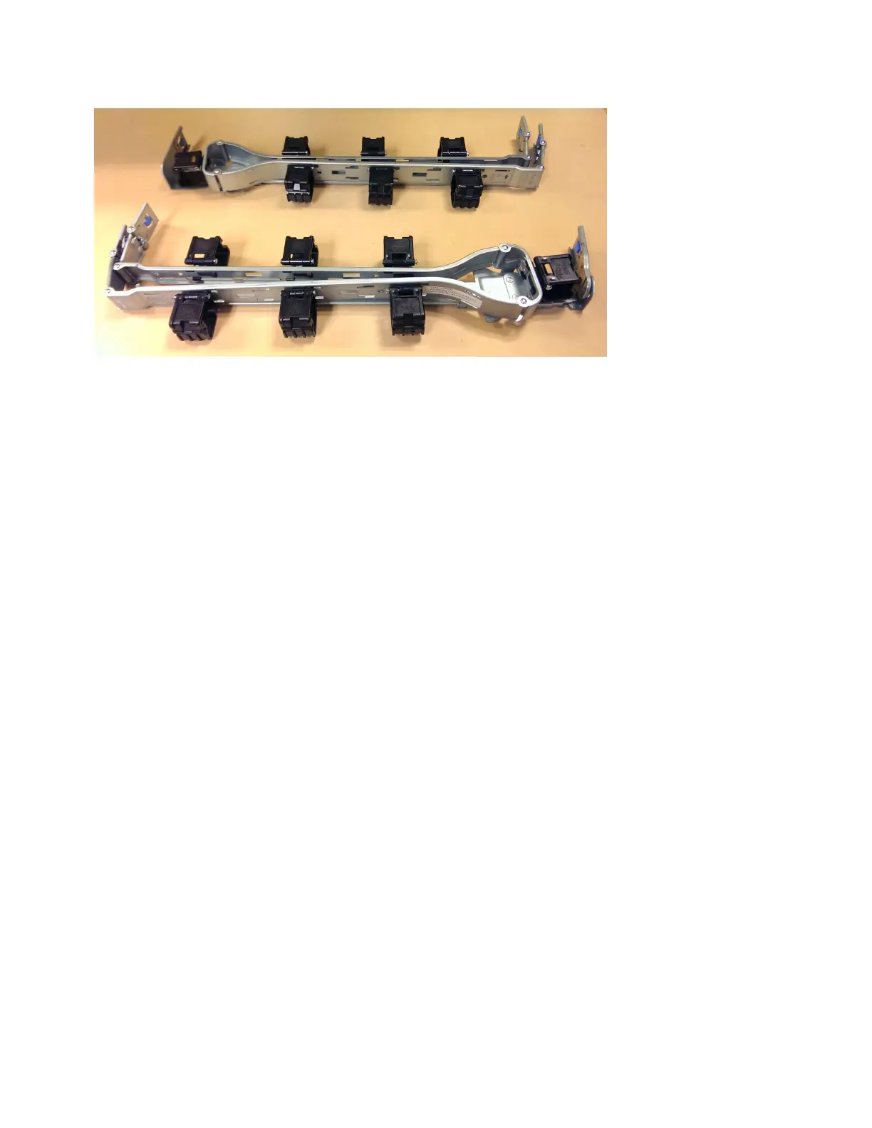
Remove the upper CMA assembly
The connectors of the CMA are installed on the rail hooks at the end of the
support rails. Figure 43 on page 63 shows the connectors on the upper CMA
assembly.
svc01017
Figure 42. Upper and lower cable-management arms
62 Storwize V5000 Gen2: Quick Installation Guide

Table of Contents

Questions and Answers:

Question and Answer IconNeed help?

Do you have a question about the IBM Storwize V5000 Gen2 and is the answer not in the manual?

IBM Storwize V5000 Gen2 Specifications

General IconGeneral
ModelStorwize V5000 Gen2
Storage TypeHybrid Flash Array
Form Factor2U
Maximum Drives240
Operating SystemIBM Spectrum Virtualize
Drive TypesSSD
RAID Levels0, 1, 5, 6, 10
Host Interface8 Gbps Fibre Channel (FC), 16 Gbps Fibre Channel (FC), 10 Gbps iSCSI, 12 Gbps SAS
Drive Bays24
Cache MemoryUp to 64 GB
Power SupplyRedundant, hot-swappable power supplies
VirtualizationYes

Related product manuals