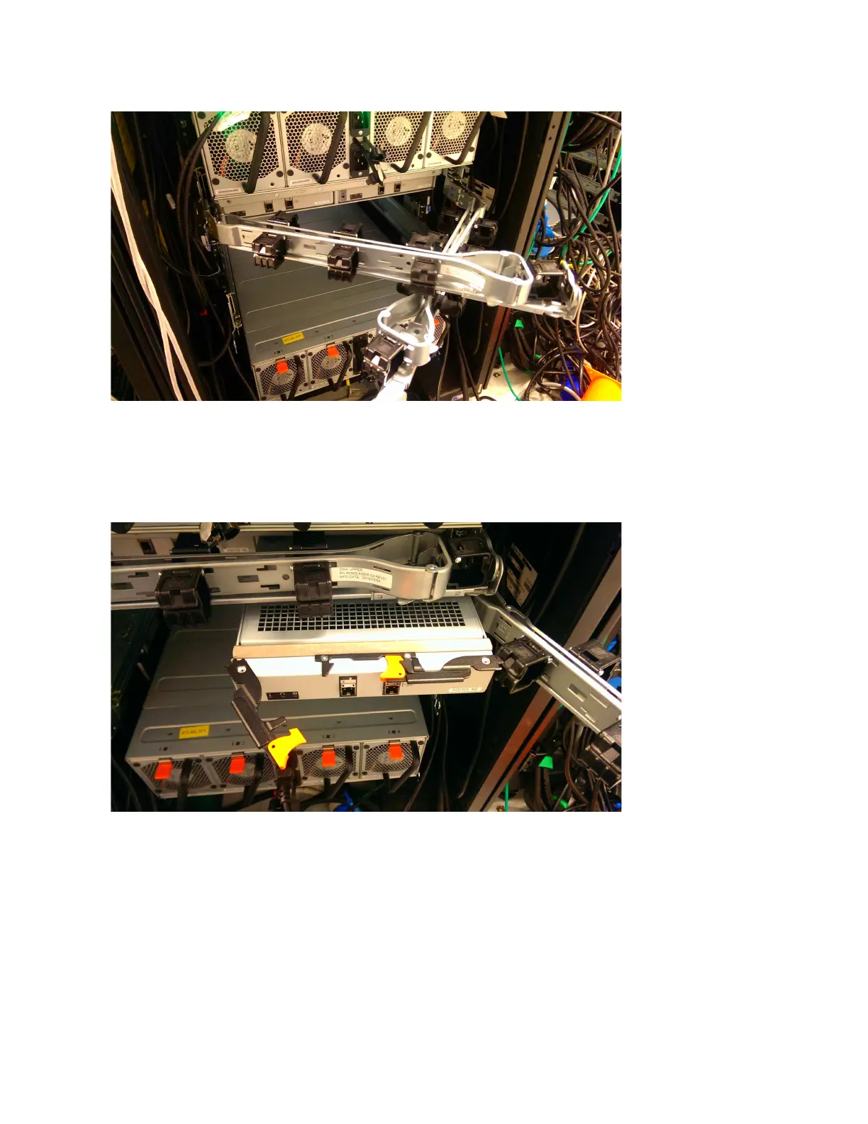
Figure 46 shows that the lower CMA assembly is swung away from the rear of the
enclosure so that the expansion canister is accessible.
Procedure
1. To release the upper CMA, push the latch on the support rail connector ▌5▐ to
release it from the connector base ▌6▐ on the right rail.
Figure 45. Upper and lower CMA assemblies moved aside
Figure 46. Lower CMA assembly moved
Chapter 2. Installing the system hardware 65

 Loading...


