Power
Faults
See
the
section,
Power
System
Service
Checks,
in
this
manual.
Loading
Faults
See
the
section
on
FLTs
in
this
manual.
Remember
that
none
of
the
central
processing
unit
and
very
little
of
the
channel
circuitry
is
used
to load
FLTs.
·
Programming
Faults
and
Error
Stops
Programming
faults
and
error
stop
approaches
to
troubleshooting
are
shown. Note that:
1.
The
machine
status
is
logged
out
before
begin-
ning
a
troubleshooting
sequence.
2.
FLT's
are
run
before
functional
tests.
OTHER MAINTENANCE DOCUMENTATION
Error
Check
Analysis
Diagrams
Error
check
analysis
diagrams
(ECAD' s)
are
com-
puter-drawn,
engineering
controlled,
schematic
representations
of the
error
register
and the
cir-
cuitry
behind
each
possible
error
indication.
AL6
1 ---------
~
TR20
H
3
5
Position 4
----
6
ECAD's
are
in Volume 1
Reference
of
Systems
Diagrams.
To
use
ECAD's,
turn
to
page
UCA101
and
find
your
particular
error
in the
error
register
block
diagram.
The
numbers
to the
left
of the
error
register
lead
you
to
an ECAD
specifically
tailored
for
that
error.
Further
to
the
left
is
the ALD
page
number
of the
parity
checker
for
that
error.
Each
ECAD
contains
a block
diagram
simplified
to show the
basic
logic of the
error
checking
circuit
and
a
list
of
ROS
functions that
pertain
to
the
circuit.
In addition,
basic
timings,
scope
points,
pertinent
notes,
and the
complete
logic
for
at
least
one
bit
position
of the
error
circuit
are
shown
wherever
necessary.
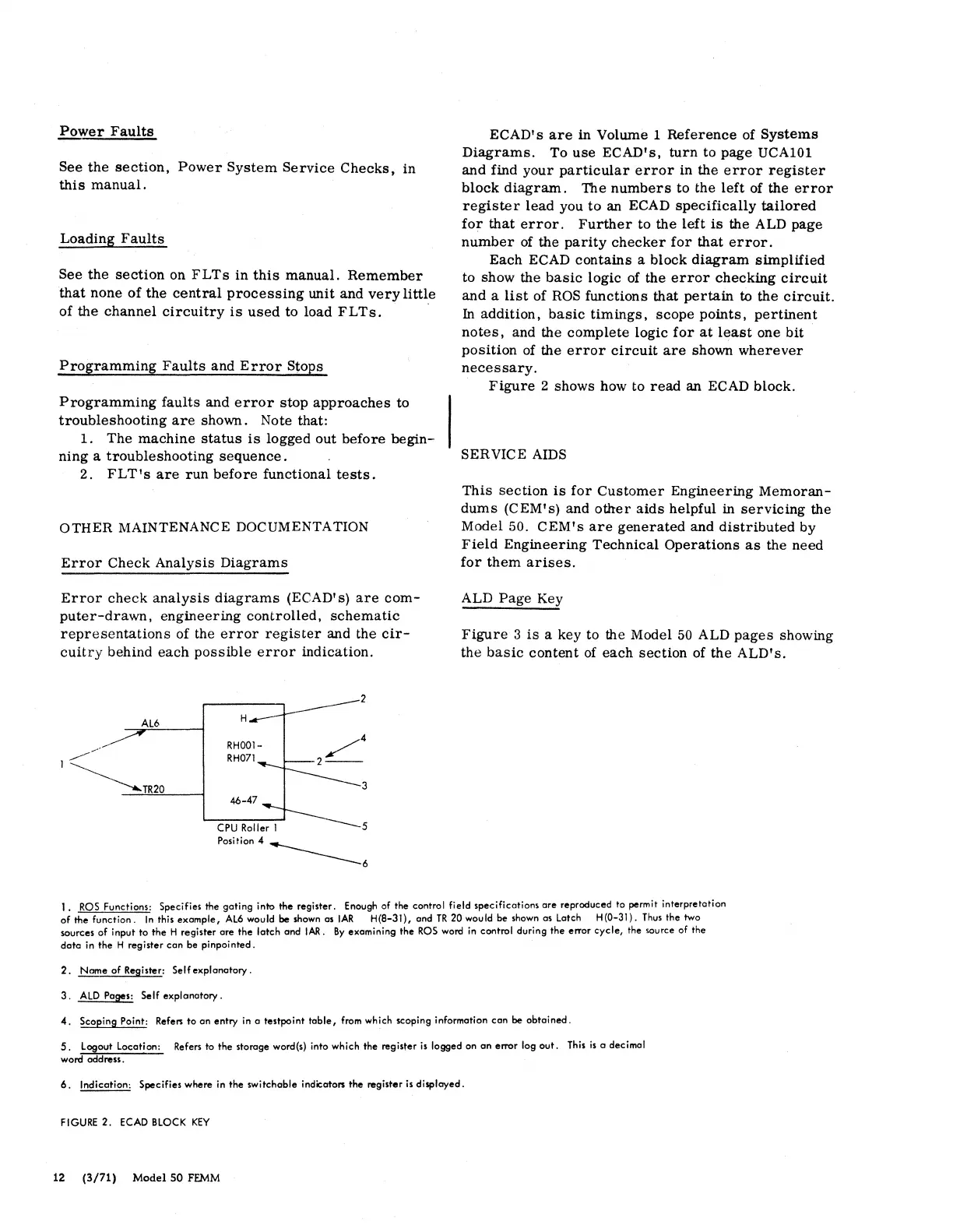
Figure
2 shows how to
read
an
ECAD block.
SERVICE AIDS
This
section
is
for
Customer
Engineering
Memoran-
dums
(CEM's)
and
other
aids
helpful in
servicing
the
Model 50.
CEM's
are
generated
and
distributed
by
Field
Engineering
Technical
Operations
as
the need
for
them
arises.
ALD
Page
Key
Figure
3
is
a key to the Model
50
ALD
pages
showing
the
basic
content
of
each
section
of
the
ALD's.
1.
ROS
Functions: Specifies the goting into the register. Enough of the control field specifications are reproduced to permit interpretation
of
the function.
In
this example,
AL6
would
be
shown
as
IAR
H(B-31), and
TR
20 would be shown as Latch H(0-31).
Thus
the two
sources
of
input to
the
H register are
the
latch and
IAR.
By
examining the
ROS
word in control during the error cycle, the source of the
data
in the H register can be pinpai
nted.
2.
Name
of
Register: Self explanatory.
3.
ALO
Pages: Self explanatory.
4.
Scoping Paint: Refers
to
an entry in a testpaint
table,
from which scoping information can
be
obtained.
5. Logout Location: Refers ta the storage word(s) into which the register
is
logged on
an
error log
out.
This
is
a decimal
word address.
6.
Indication: Specifies where in
the
switchable indicators the register
is
displayed.
FIGURE
2.
ECAD
BLOCK
KEY
12
(3/71)
Model
SO
FEMM