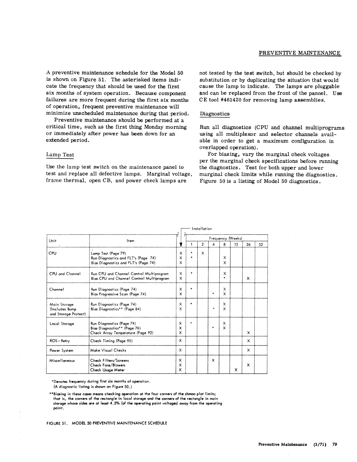
A
preventive
maintenance
schedule
for
the
Model
50
is
shown on
Figure
51. The
asterisked
items
indi-
cate
the frequency
that
should be
used
for
the
first
six
months of
system
operation.
Because
component
failures
are
more
frequent
during
the
first
six
months
of
operation,
frequent
preventive
maintenance
will
minimize
unscheduled
maintenance
during
that
period.
Preventive
maintenance should be
performed
at
a
critical
time,
such
as
the
first
thing Monday
morning
or
immediately
after
power has
been
down
for
an
extended
period.
Lamp
Test
Use
the
lamp
test
switch on the maintenance panel to
test
and
replace
all defective
lamps.
Marginal voltage,
frame
thermal,
open CB, and
power
check
lamps
are
PREVENTIVE
MAINTENANCE
not
tested
by the
test
switch, but should be
checked
by
substitution
or
by duplicating
the
situatio'l
that
would
cause
the
lamp
to
indicate.
The
lamps
are
pluggable
and
can
be
replaced
from
the
front
of the pannel. Use
CE
tool #461420
for
removing
lamp
assemblies.
Diagnostics
Run
all
diagnostics
(CPU and channel
multiprograms
using
all
multiplexor
and
selector
channels
avail-
able
in
order
to
get
a
maximum
configuration
in
overlapped
operation).
For
biasing,
vary
the
marginal
check
voltages
per
the
marginal
check
specifications
before
running
the
diagnostics.
Test
for
both
upper
and
lower
marginal
check
limits
while running
the
diagnostics.
Figure
50
is
a
listing
of Model
50
diagnostics.
.------ lnsta
II
at
ion
l
fl
Frequency (Weeks)
Unit
Item
CPU
Lamp
Test (Page 79)
Run
Diagnostics and
FLT's
(Page 74)
Bias
Diagnostics and
FL
T's
(Page 74)
CPU and Channel
Run
CPU
and Channel Control Multiprogram
Bias
CPU
and Channel Control Multiprogram
Channel
Run
Diagnostics (Page 74)
Bias
Progressive Scan (Page 74)
Main Storage
Run
Diagnostics (Page 74)
(Includes
Bump
Bias
Diagnostics** (Page 84)
and Storage Protect)
Local Storage
Run
Diagnostics (Page 74)
Bias
Diagnostics** (Page 76)
Check Array
Te1T1perature
(Page 92)
ROS-
Retry Check Timing (Page 95)
Power System
Make Visual Checks
Miscellaneous Check Filters/Screens
Check Fans/Blowers
Check Usage Met er
*Denotes frequency during first six months
of
operation.
(A
diagnostic listing is shown on Figure
50.)
1
1 2 4
x
.
x
x
.
x
x
.
x
x
.
x
.
x
.
x
.
x
.
x
.
x
x
x
x x
x
x
**Biasing in these cases means checking operation at
the
four corners
of
the
shmoo plot limits;
that
is,
the
earners of the
rectangle
in local storage and
the
corners of
the
rectangle
in
main
storage whose sides
are
at least
4.5%
(of
the
operating point voltages) away from
the
operating
point.
FIGURE
51.
MODEL
50
PREVENTIVE
MAINTENANCE
SCHEDULE
8
13
x
x
x
.
x
x
x
x
x
x
x
26
52
x
x
x
x
x
Preventive Maintenance
(3/71)
79