FLT
Hex Mode
Op
Reg
Op
Code Usage
000000 00
MS
000001
01
*
MS
000010 02* MS/ROS
000011 03*
000100 04*
000101 05*
000110 06
000111 07
001000 08
001001 09
001010
OA
001011
OB
001100
OC*
001101
OD
001110
OE
001111
OF
010000 10*
010001 11*
110001 31*
010010 12*
010011 13*
010100 14*
010101 15*
110101 35*
010110 16*
110110 36*
010111 17*
110111 37*
011000 18*
011001 19*
011010
lA*
011011
1
B*
011100
lC*
011101
10*
011110 1
E*
011111 1 F
MS
MS
MS/ROS
MS
MS
MS
MS
MS/ROS
MS
MS/ROS
MS/ROS
MS
MS
ROS
ROS
ROS
ROS
}
ROS
ROS
ROS
ROS
ROS
ROS
ROS
ROS
ROS
ROS
ROS
ROS
ROS
ROS
ROS
ROS
Operation
No
op.
ROSDR
group 1 (0-30) to
SOR
and
OR
with next word
from
storage.
ROSDR
group 2 (31-55) to
SOR
and OR
with
next
word
from
storage.
ROSDR
group 3 (56-87) to
SOR
and
OR
with next word
from
storage.
ROSDR
group 4 (88-97) to
SOR
and
OR
with
next
word
from
storage.
ROAR
to
SOR
(6-17) and
OR
with next
ward (mask)
from
storage .
Request for
ROS
mode,
SOR
(19-30) to
ROAR,
reset binary
tgr.
Reset error reg and binary
tgr.
No
op.
Call
for
FLT
load.
lnh ibit
SAR
clock
(to
stop--
loops on
same word
in
SOR).
To
continue
oper-
ation,
press
start
pushbutton,
Error
reg
ta
SOR
(0-31),
Na
op or
LCS
information to
SOR
(0-8).
SOR
(12-31)
to
IAR
if binary tgr
is
off
(causes branch to specified address +4),
Step binary tgr if
SOR
is
all
l's.
SAR
and byte slots to
SOR
(0-31
),
L (0-27) plus parity bit$
ta
SOR
(0-31).
L (28-31)
ta
SOR
(24-27) "L reg
fold,"
Selector
channel sfatus to
SOR
(0-31).
GP stats (0-3)
are
used with these codes
to further specify what status
is
used.
Stats, byte
counters,
etc.
to
SOR
(0-31),
H (0-27) plus parity
bi
ti
to
SOR
(0-31).
H (28-31) to
SOR
(24-27) "H reg
fold."
M (0-27) plus
parity
bit>
to
SOR
(0-31).
M (28-31) to
SOR
(24-27) "M reg
fold."
R (0-27) plus
parity
bits to
SOR
(0-31).
R (28-31) to
SOR
(24-27)
"R
reg
fold."
LSAR,
LSFR,
counters,
etc.
to
SOR
(0-31).
Mpx
channel (group
1)
to
SOR
(0-31).
Mpx
channel (group 2) to
SOR
(0-31),
Mpx channel (group
3)
to
SOR
(0-31).
Common
channel
(group 1) to
SOR
(0-31).
Common channel (group 2) to
SOR
(0-31).
Common
channel
(group 3) to
SOR
(0-31).
No op.
NOTES: The
FLT
op reg
is
a part
of
the
scan/log
decoder
(Figure 11). More
detailed
information on the functions
af
these
op
codes
is
shown on Figure
12.
*All these
op
codes send
data
to the
SOR
via the
scan bus.
See
Figure
13.
FIGURE 10.
FLT
OP
REG
INSTRUCTIONS
22
(3/71)
Model
50
FEMM
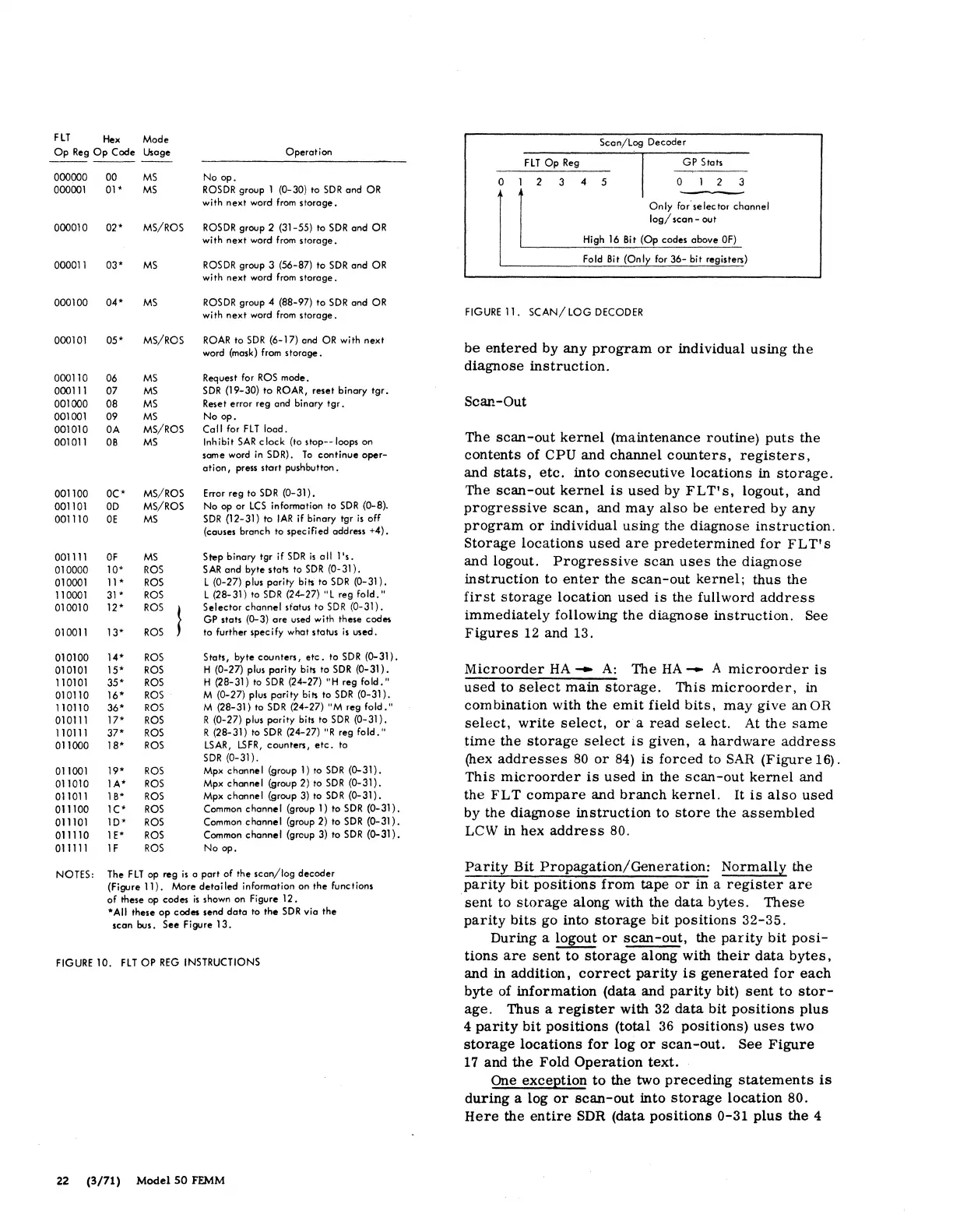
Seen/Log Decoder
FLT
Op
Reg
GP Stats
0 1 2 3 4 5 0 2 3
Only
for
selector channel
log/
seen - out
High
16
Bit (Op codes above
OF)
Fold Bit (Only for
36-
bit registers)
FIGURE
11.
SCAN/
LOG
DECODER
be
entered
by
any
program
or
individual
using
the
diagnose
instruction.
Scan-Out
The
scan-out
kernel
(maintenance routine)
puts
the
contents
of CPU
and
channel
counters,
registers,
and
stats,
etc.
into
consecutive
locations
in
storage.
The
scan-out
kernel
is
used
by
FLT's,
logout, and
progressive
scan,
and
may
also
be
entered
by
any
program
or
individual
using
the diagnose
instruction.
Storage
locations
used
are
predetermined
for
FL
T
1
s
and logout.
Progressive
scan
uses
the
diagnose
instruction
to
enter
the
scan-out
kernel;
thus the
first
storage
location
used
is
the fullword
address
immediately
following the diagnose
instruction.
See
Figures
12 and 13.
Microorder
HA
-
A:
The
HA
- A
microorder
is
used
to
select
main
storage.
This
microorder,
in
combination with
the
emit
field
bits,
may
give
anOR
select,
write
select,
or
a
read
select.
At
the
same
time
the
storage
select
is
given, a
hardware
address
(hex
addresses
80
or
84)
is
forced
to
SAR
(Figure
16).
This
microorder
is
used
in the
scan-out
kernel
and
the
FLT
compare
and
branch
kernel.
It
is
also
used
by the
diagnose
instruction
to
store
the
assembled
LCW in hex
address
80.
Parity
Bit
Propagation/Generation:
Normally
the
parity
bit
positions
from
tape
or
in a
register
are
·sent
to
storage
along with the
data
bytes.
These
parity
bits
go into
storage
bit
positions
32-35.
During a logout
or
scan-out,
the
parity
bit
posi-
tions
are
sent
to
storage
along with
their
data
bytes,
and in addition,
correct
parity
is
generated
for
each
byte of
information
(data .and
parity
bit)
sent
to
stor-
age.
Thus a
register
with 32
data
bit
positions
plus
4
parity
bit
positions
(total
36
positions)
uses
two
storage
locations
for
log
or
scan-out.
See
Figure
17
and
the
Fold
Operation
text.
One exception
to
the two
preceding
statements
is
during
a log
or
scan-out
into
storage
location
80.
Here
the
entire
SDR (data
positions
0-31
plus
the 4