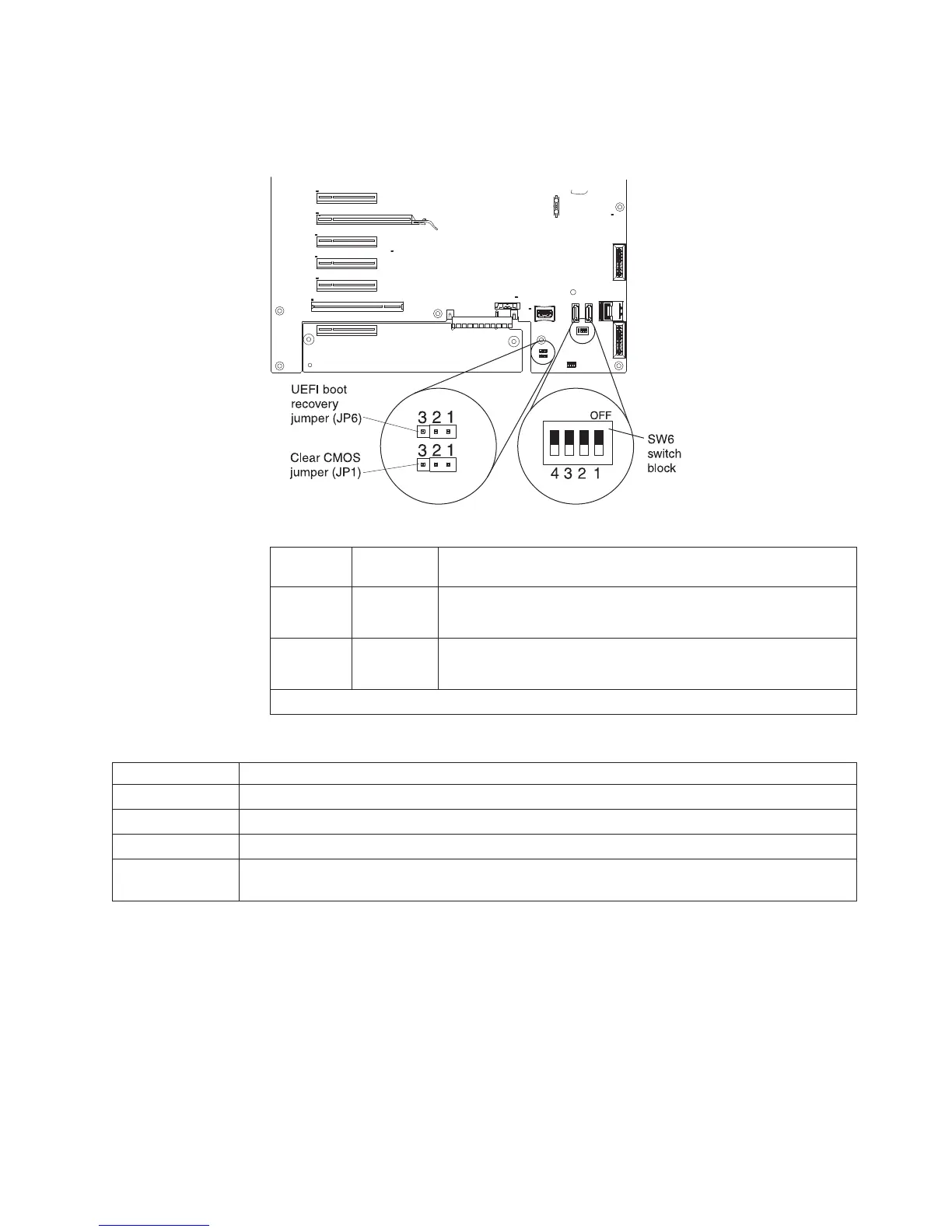
System-board switches and jumpers
The following illustration shows the SW6 switch and the jumpers on the system
board. See the tables below the illustration for information about the switch settings.
Table 3. System-board jumpers
Jumper
number
Jumper
name Jumper setting
JP1 CMOS clear
v Pins 1 and 2: Normal operation (default).
v Pins 2 and 3: Clears CMOS memory.
JP6 UEFI boot
recovery
v Pins 1 and 2: Normal operation (default).
v Pins 2 and 3: Enable the UEFI recovery mode.
Note: If no jumper is present, the server responds as if the jumpers is on pins 1 and 2.
Table 4. System-board switch 6
SW 6 Switches Switch description
1 Reserved (default off)
2 Power-on password override when on (default off)
3 Reserved (default off)
4 When this switch is off, the primary IMM firmware ROM page is loaded. When this switch is on,
the secondary (backup) IMM firmware ROM page is loaded (default off).
Notes:
1. Before you change any switch settings or move any jumpers, turn off the server;
then, disconnect all power cords and external cables. (Review the information in
“Safety” on page v, “Installation guidelines” on page 35, and “Handling
static-sensitive devices” on page 37.)
2. Any system-board switch or jumper blocks that are not shown in the illustrations
in this document are reserved.
The following illustration shows the SW 5 switch and the jumpers on the system
board. See the tables below the illustration for information about the switch settings.
Chapter 2. Installing optional devices 23

 Loading...


