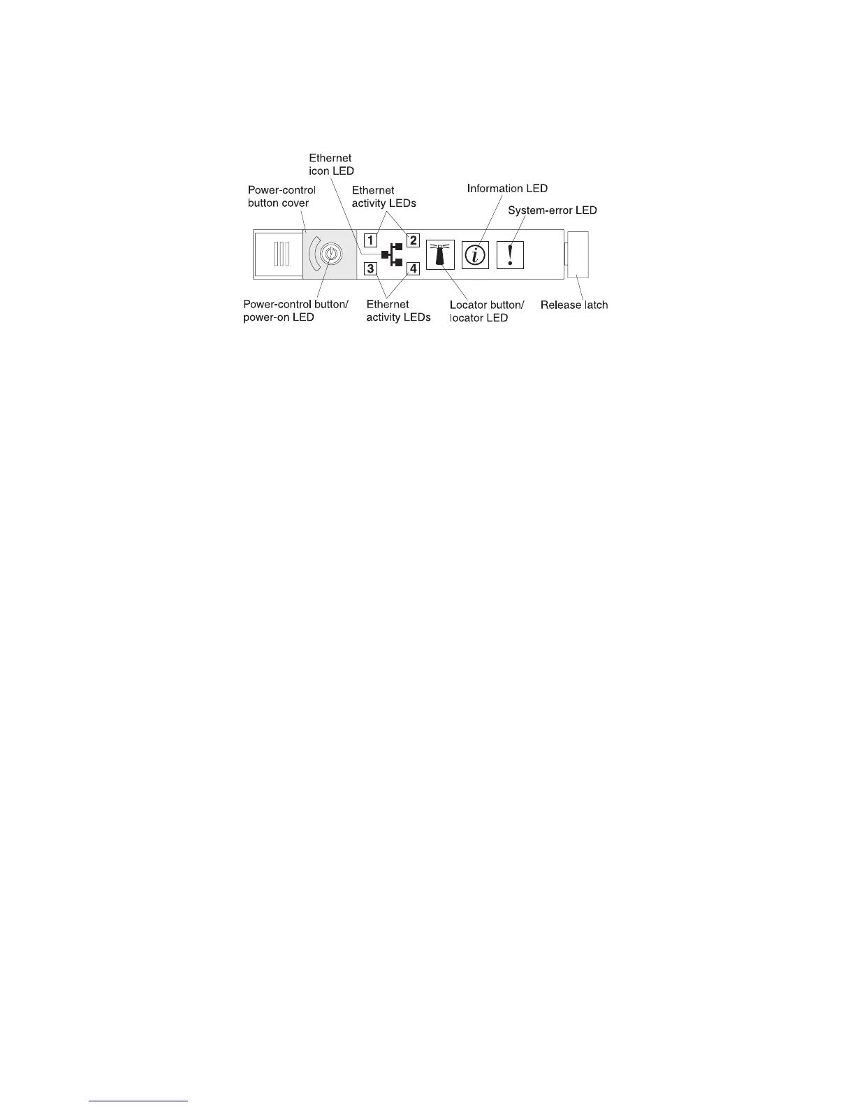
Operator information panel
The following illustration shows the controls and LEDs on the operator information
panel.
The following controls and LEDs are on the operator information panel:
v Power-control button and power-on LED: Press this button to turn the server
on and off manually or to wake the server from a reduced-power state. The
states of the power-on LED are as follows:
Off: AC power is not present, or the power supply or the LED itself has failed.
Flashing rapidly (4 times per second): The server is turned off and is not
ready to be turned on. The power-control button is disabled. This will last
approximately 20 to 40 seconds.
Note: Approximately 40 seconds after the server is connected to ac power,
the power-control button becomes active.
Flashing slowly (once per second): The server is turned off and is ready to
be turned on. You can press the power-control button to turn on the server.
Lit: The server is turned on.
Fading on and off: The server is in a reduced-power state. To wake the
server, press the power-control button or use the IMM Web interface. For
information about logging on to the IMM Web interface, see “Logging on to
the Web interface” on page 155.
v Ethernet icon LED: This LED lights the Ethernet icon.
v Ethernet activity LEDs: When any of these LEDs is lit, it indicates that the
server is transmitting to or receiving signals from the Ethernet LAN that is
connected to the Ethernet port that corresponds to that LED.
v Information LED: When this LED is lit, it indicates that a noncritical event has
occurred. An LED on the light path diagnostics panel is also lit to help isolate the
error.
v System-error LED: When this LED is lit, it indicates that a system error has
occurred. An LED on the light path diagnostics panel is also lit to help isolate the
error.
v Release latch: Slide this latch to the left to access the light path diagnostics
panel, which is behind the operator information panel.
v Locator button and locator LED: Use this LED to visually locate the server
among other servers. Press this button to turn on or turn off this LED locally. You
can use IBM Systems Director to light this LED remotely.
Light path diagnostics panel
The light path diagnostics panel is on the top of the operator information panel.
Chapter 1. The System x3650 M3 server 15

 Loading...


