Table 3. System board jumpers (continued)
Jumper
number
Jumper
name Jumper setting
J147 IMM
recovery
jumper
v Pins 1 and 2: Normal (default) Loads the primary IMM
firmware ROM page.
v Pins 2 and 3: Loads the secondary (backup) IMM firmware
ROM page.
Notes:
1. If no jumper is present, the server responds as if the pins are set to 1 and 2.
2. Changing the position of the UEFI boot recovery jumper from pins 1 and 2 to pins 2 and
3 before the server is turned on alters which flash ROM page is loaded. Do not change
the jumper pin position after the server is turned on. This can cause an unpredictable
problem.
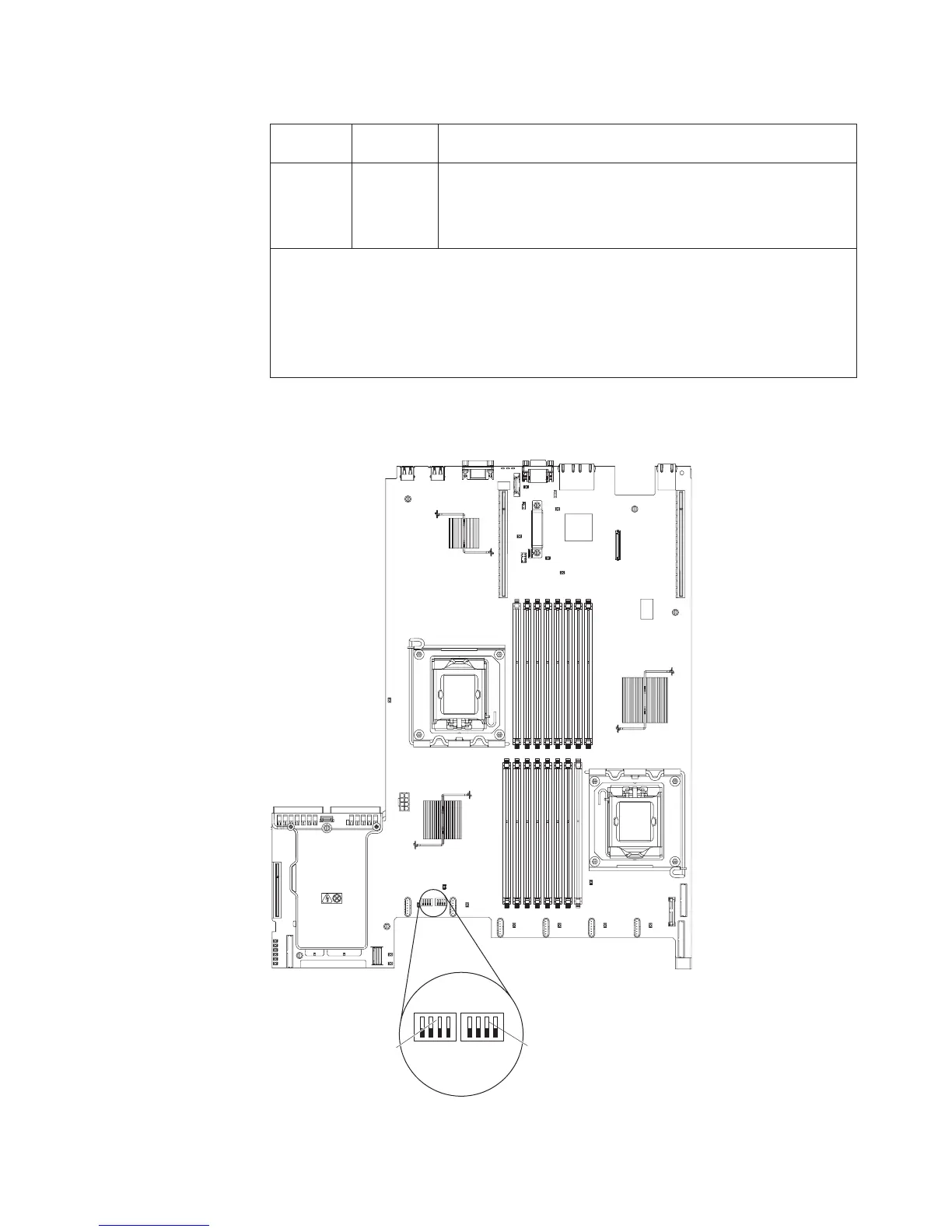
The following illustration shows the jumper settings for switch blocks SW3 and SW4
on the system board.
SW3 switch blockSW4 switch block
1234 1234
Off Off
Table 4 on page 32 and Table 5 on page 32 describe the function of each switch on
SW3 and SW4 switch blocks on the system board.
Chapter 2. Installing optional devices 31
 Loading...


