2030 LCD panel
For access, remove these FRUs, in order:
v “1010 Battery pack” on page 59
v “1020 Mini PCI adapter” on page 60
v “1030 Communication daughter card (CDC)” on page 63
v “1040 Backup battery” on page 70
v “1060 Hard-disk drive” on page 72
v “1070 Ultrabay Plus device” on page 74
v “1080 Ultrabay 2000 device” on page 75
v “1090 Keyboard” on page 76
v “1100 Keyboard CRU insulator” on page 80
v “1110 Keyboard bezel” on page 81
v “1120 Hinge cover” on page 86
v “1150 Ultrabay Plus slot” on page 91
v “1190 LCD assembly” on page 101
v “2010 Front bezel” on page 115
v “2020 Inverter card” on page 117
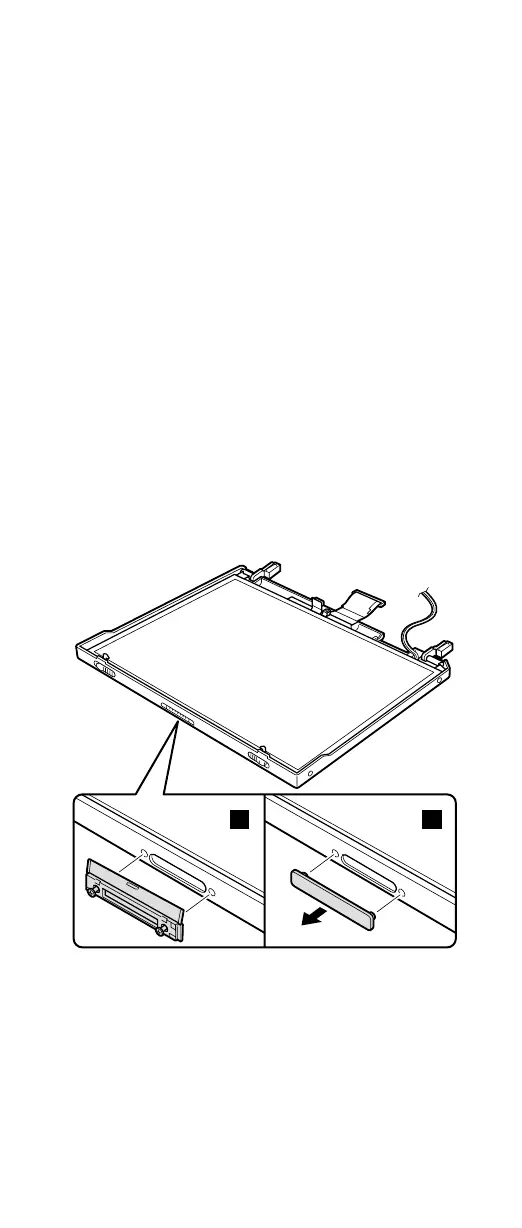
Remove the UltraPort adapter if it has been screwed onto
the LCD. To do this, remove the screws from the ends of
the screw from both side of the adapter as shown in figure
1a. Remove the connector cover for the others as shown
in figure 1b.
1a 1b
(continued)
Removing and replacing a FRU
ThinkPad A30, A30p 119