Table 2. Switches on SW4 (continued)
Switch number Description
2 Clear CMOS:
v Leave the switch in the off position to keep the CMOS
data.
v Move the switch to the on position to clear the CMOS
data, which clears the power-on password and
administrator password.
Notes:
1. Before you change any switch settings or move any jumpers, turn off the server;
then, disconnect all power cords and external cables. (Review the information in
“Safety” on page v, “Installation guidelines” on page 21, and “Handling
static-sensitive devices” on page 22.)
2. Any system-board switch or jumper blocks that are not shown in the illustrations
in this document are reserved.
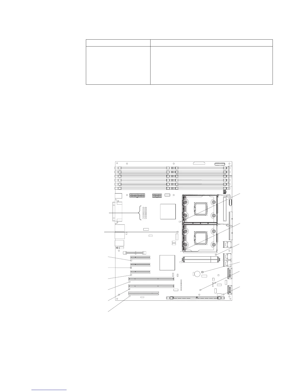
System-board LEDs
The following illustration shows the LEDs on the system board.
Slot 1
error LED
Slot 2
error LED
Slot 3
error LED
Slot 4
error LED
Slot 5
error LED
Slot 6
error LED
Microprocessor
mismatch
LED
DIMM
error LEDs
1 thru 12
Microprocessor 1
error LED
Microprocessor 2
error LED
VRM error
LED
BMC heartbeat
LED
ServeRAID-8k
error LED
Battery error LED
Chapter 2. Installing optional devices 15
 Loading...