iC-TW29 26-BIT ENCODER PROCESSOR
WITH INTERPOLATION AND BiSS INTERFACE
Rev C1, Page 23/28
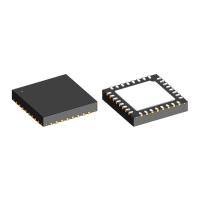
SIN+
SIN–
COS+
COS–
iC-TW29
AVDD
PSIN
NSIN
PCOS
NCOS
iC-SMxL
Sensor
Figure 18: Magnetic Sensor Connection
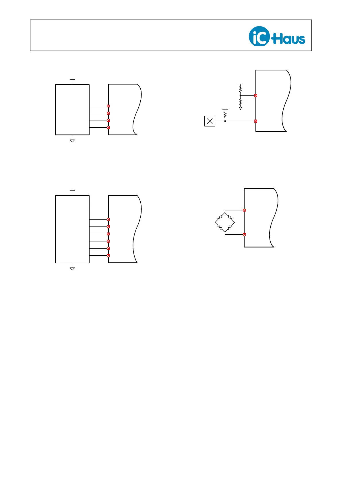
SIN+
SIN–
COS+
COS–
iC-TW29
5V
PA
NA
PB
NB
iC-PT…H
Sensor
ZERO+PZ
ZERO–NZ
Figure 19: Optical Sensor Connection
Nominal differential signal amplitudes between 20 mV
and 2.0 V in two ranges can be accommodated.
ZERO Inputs
The iC-TW29 can interface to a wide range of differen-
tial or single-ended index or zero sensors to provide a
Z output which is synchronized with the AB outputs or
to reset the gearbox counter. Optical sensors usually
provide differential zero or index signals along with the
sin/cos signals. In magnetic systems, a separate zero
sensor is usually required.
Digital zero sensors (Hall, MR, and others) typically pro-
vide a single-ended active-low signal via an open-drain
output that pulls low in the presence of a magnetic eld.
Connect active-low (open drain) digital index sensors to
the iC-TW29 ZERO– input and connect the ZERO+ in-
put to VDD/2 using a resistive voltage divider as shown
in Figure 20.
ZERO+
ZERO-
DVDD
iC-TW29
Digital Hall
active low
AVDD
Figure 20: Digital Index Sensor Connection
Analog-output zero sensors, such as MR bridges, can
also be used with the iC-TW29 as shown in Figure 21.
iC-TW29
MR Index
Sensor
ZERO+
ZERO-
Figure 21: Analog Index Sensor Connection
To produce a Z output once every input cycle, connect
ZERO+ to 3.3 V and ZERO– to ground. This is use-
ful in on-axis applications where one input revolution
produces only one input cycle.
If no Z output from the iC-TW29 is required, connect
ZERO+ to ground and ZERO– to 3.3 V.