iC-TW29 26-BIT ENCODER PROCESSOR
WITH INTERPOLATION AND BiSS INTERFACE
Rev C1, Page 24/28
ABZ Outputs
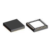
The iC-TW29 can be congured to provide differential
ABZ outputs capable of driving 20 mA into a terminated
RS422 line. The A+, A–, B+, B–, Z+, and Z– outputs
can be directly connected to the RS422 line as shown
in Figure 22.
120 Ω
120 Ω
120 Ω
A+
A–
B+
B–
iC-TW29
Z+
Z–
A+
B+
Z+
A–
B–
Z–
Figure 22: ABZ Output Connection
The three signal pairs should be terminated with a 120
Ω
resistor at the far (receiving) end of the cable as shown.
The RS422-compatible line driver can be disabled to
save power for local or short-run applications. In this
case, termination resistors should not be used.
UVW Outputs
The iC-TW29 can be congured to provide differential
UVW outputs or simultaneous single-ended ABZ and
UVW outputs.
xRST Input
The iC-TW29 contains a built-in power-on-reset (POR)
circuit that controls the safe startup of the device. In
most applications, no external components are required
and xRST can be connected directly to 3.3 V.
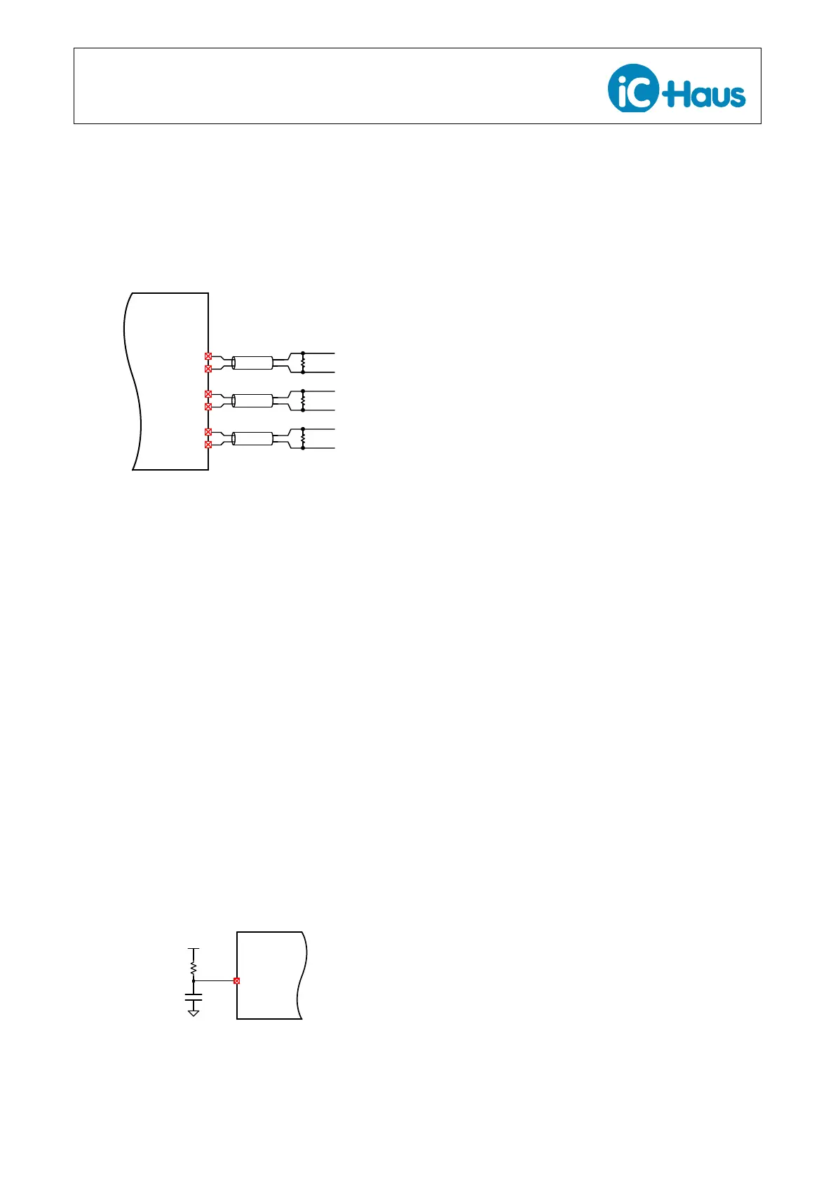
Alternatively, an RC network with recommended values
of 47 k
Ω
and 100 nF can be connected to the active-low
xRST input to extend device reset in case of a slow-ris-
ing supply as shown in Figure 23.
DVDD
xRST
iC-TW29
47 kΩ
100 nF
Figure 23: xRST Connection
In stand-alone applications, it is recommended to al-
ways provide for an RC network on the PC board and
only populate the capacitor if required. Without the
capacitor, the resistor provides the necessary pull-up.
In hosted applications, the xRST input is best controlled
by the host. For battery-powered applications, the host
can hold xRST low to reduce power consumption (low
power mode). See spec. item 005.
xIRQ
In stand-alone applications, xIRQ functions as an ac-
tive-low fault output. It can be used to directly drive
an LED with an appropriate current-limiting resistor for
fault indication.
In hosted applications, xIRQ can be connected to an
interrupt request input on the host processor. In this
way, when a warning or fault occurs, the host processor
can query the iC-TW29 to determine what action to
take. xIRQ can also be congured as an external fault
input.
xIRQ can be congured as an open-drain output allow-
ing a wired-OR connection of multiple iC-TW29s to a
single interrupt request input on the host processor.
Finally, xIRQ can be congured as an external interrupt
request input.
LED Output
The iC-TW29 can be congured to provide LED inten-
sity control for optical sensors. The LED output func-
tions as a high-current output to drive the illumination
LED used with an optical sensor.
If the LED intensity control functionality is not needed,
the LED output can be congured for use as gener-
al-purpose I/O.
BiSSEN Input
The BiSSEN input is used to enable the TW29’s BiSS
interface. Connect BiSSEN to 3.3 V to enable the BiSS
interface; connect BiSSEN to ground to disable the
BiSS interface. Regardless of the EEPROM congu-
ration data, the I/O pins A+, B+, Z+ are used for MA,
SLO, SLI.
General-Purpose I/O
The GPIO pin can be congured as a general-purpose
input or output. If congured as an input, it can be
further congured as a BiSS position preset input. In
this case, a push-button and pull-up resistor can be
connected to this input for easy manual presetting.