iC-TW29 26-BIT ENCODER PROCESSOR
WITH INTERPOLATION AND BiSS INTERFACE
Rev C1, Page 20/28
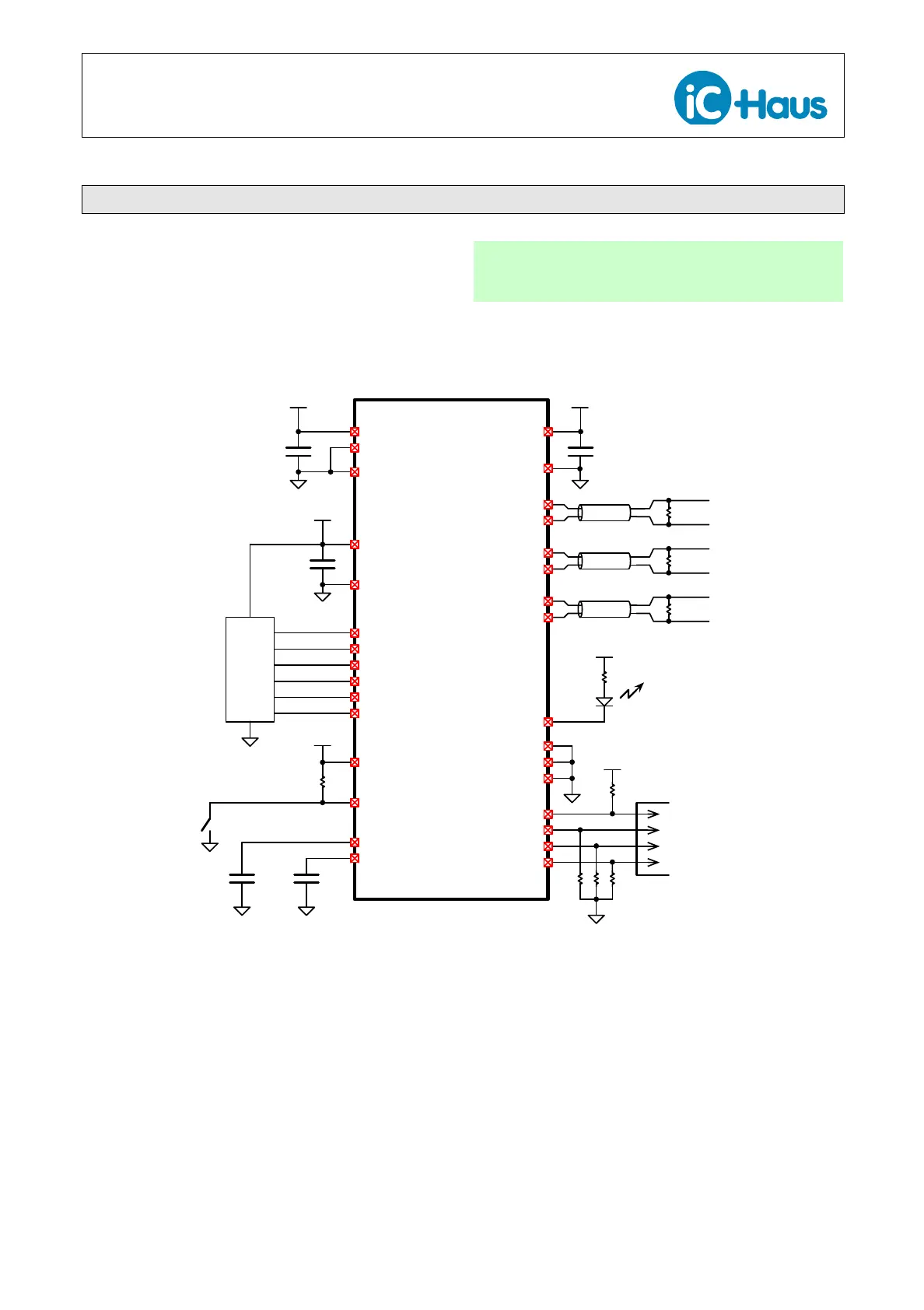
ELECTRICAL CONNECTIONS
The basic electrical connections for an incremental
stand-alone application with differential ABZ outputs
are shown in Figure 15. Other than the sin/cos sensor,
only a few bypass capacitors and other components
are required for operation.
Application Hint
The input voltages must not exceed the chip’s supply
voltage (3.3 V).
VREF
VC
100
nF
1µF
AVDD
AVSS
3.3V
SIN+
SIN–
COS+
COS–
Sensor
iC-TW29
xSS
SCLK
SI
SO
SPI
Configuration
Port
xCALIB
Calibration
Button
100
nF
1µF
IOVDD
3.3V
IOVSS
A+
A–
B+
B–
Z+
Z–
1µF
DVDD
DVSS
3.3V
BISSEN
ZERO+
ZERO–
xRST
3.3V
xIRQ
Fault LED
Differential
RS422
ABZ Outputs
GPIO
RESERVED
RESERVED
3.3V
120 Ω
120 Ω
120 Ω
xSS
SCLK
MOSI
MISO
3.3V
Figure 15: Typical Electrical Connections For Incremental Stand-Alone Application


 To Next Page