iC-TW29 26-BIT ENCODER PROCESSOR
WITH INTERPOLATION AND BiSS INTERFACE
Rev C1, Page 21/28
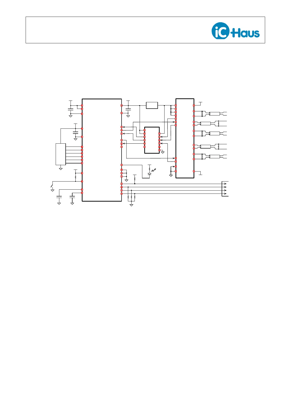
The basic electrical connections for an absolute mul-
titurn stand-alone application using BiSS are shown
in Figure 16. An external RS422-compatible driver/re-
ceiver, such as the iC-HF, and a 5 V-to-3.3 V level shifter,
such as the TXS0104E, is required. An external mul-
titurn device, such as the iC-PVL, is connected to the
absolute data interface.
VREF
VC
100
nF
1µF
AVDD
AVSS
3.3V
SIN+
SIN–
COS+
COS–
Sensor
iC-TW29
xSS
SCLK
SI
SO
SPI
Configuration
Port
xCALIB
Calibration
Button
100
nF
1µF
IOVDD
3.3V
IOVSS
SLI (Z+)
Clk Out (A–)
Data In (B–)
GPIO (Z–)
1µF
DVDD
DVSS
3.3V
BISSEN
ZERO+
ZERO–
xRST
3.3V
xIRQ
Fault
LED
BiSS
Slave
Interface
GPIO
RESERVED
RESERVED
3.3V
xSS
SCLK
MOSI
MISO
3.3V
iC-HF
X4
X3
X2
X6
X5
X1
CLK+
120 Ω
DATA+
DATA–
CLK–
Q4
NQ4
Q5
NQ5
Q2
NQ2
Q6
NQ6
Q3
NQ3
120 Ω
3.3V
Regulator
VDD
VDDS
5V
GND
GNDS
0V
MA+
SLI+
MA–
SLI–
120 Ω
120 Ω
120 Ω
SLO+
SLO–
MA (A+)
SLO (B+)
OEN
FMSEL1
FMSEL2
Absolute
Data
Interface
5VS
B1
B2
B3
A1
A2
A3
B4A4
VCCBOE
GND
VCCA
TXS0104E
Figure 16: Typical Electrical Connections For Absolute BiSS Stand-Alone Application
Alternatively, resistive voltage dividers can be used
instead of an explicit level shifter chip. In this case, val-
ues of 470
Ω
and 560
Ω
are recommended to drive MA
(A+), SLI (Z+), and Data In (B–). This will add 15 mA of
current consumption.
The BiSS interface is enabled by connecting the BiS-
SEN input pin to 3.3 V as shown. The iC-HF is used in
BiSS bus structure mode. See the iC-HF data sheet for
more information.