32
9
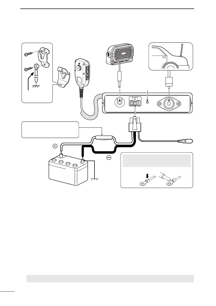
CONNECTIONS AND INSTALLATION
1MICROPHONE HANGER
Connects to the supplied microphone hanger to a vehicle’s ground to use the Mic
Hanger function. (p. 29)
2EXTERNAL SPEAKER JACK
Connectstoa4Ωexternalspeaker.
L The audio output power is typically 5 W.
3GROUND TERMINAL
Connects to a vehicle’s ground to prevent electrical shocks and interference from other
equipment occurring.
Use a screw (3 × 12 mm: not supplied).
4ANTENNA CONNECTOR
Connects to an antenna with a PL-259 connector.
A key element in the performance of any communication system is the antenna. Ask
your dealer about antennas and the best place to mount them.
CAUTION: DO NOT transmit without an antenna.
■ Connections
1
2
6
4
5
3
12 or 24 V
Battery
Red
Black
Antenna
R WARNING! NEVER
remove the fuse holder from
the DC
power cable.
Microphone
hanger cable
NOTE: Use the terminals as shown
below for the cable connections.
Crimp
Solder
Optional
speaker