3-5 POWER SUPPLY CIRCUITS
3-5-1 FRONT UNIT VOLTAGE LINE
Line Description
3.3 V
Common 3.3 V converted from the 5 V line
by the 3.3 V regulator circuit (IC151). The out-
put voltage is applied to the sub CPU (IC2003),
etc.
5 V
Common 5 V converted from the 8 V line by
the 5 V regulator circuit (IC101). The output
voltage is applied to the LCD driver (IC506),
etc.
3-3-3 2ND LO AND REFERENCE OSCILLATOR
CIRCUITS (DDS UNIT)
The reference oscillator (X1, Q1) generates a 24.8064 MHz
frequency used for the 1st LO, 3rd LO and DSP circuits as a
system clock and for the 2nd LO signal.
The oscillated signal is multiplied by 5 at Q101 and then
passed through the bandpass filter (FI101). The filtered
124.032 MHz signal is amplified at Q151 and then applied to
the 2nd mixer circuit (MAIN unit) after being passed through
the low-pass filter (L153, C154–C156) and attenuator (R157
–R159) via J151 as the 2nd LO signal.
3-3-4 3RD LO CIRCUIT (DDS UNIT)
The 3rd LO circuit generates a 3rd LO signal and shift the
frequency for the operating mode needed.
The DDS IC (IC51) generates a 10-bit digital signal. The
24.8064 MHz system clock signal from the reference oscil-
lator (X1, Q1) is buffer amplified at IC61 (pins 2, 4) and then
applied to DDS IC (IC51, pins 5, 10). The DDS IC (IC51)
generates the 438.85 kHz frequency signal and then output
from pin 10. The output signal is applied to the low-pass fil-
ter (L53, C59–C61) and then applied to the 3rd mixer circuit
(MAIN unit) via J952 (pin 13) as the 3rd LO signal.
• 3RD LO FREQUENCY
Mode
RX frequency
[kHz]
TX frequency
[kHz]
USB 440.350 440.350
LSB 437.350 437.350
CW
438.850
(–CW PITCH)
438.850
CW-R
438.850
(+CW PITCH)
438.850
RTTY 436.555* 436.555*
RTTY-R 440.975* 436.555*
AM 438.850 438.850
FM 438.850 438.850
*RTTY TONE: 2125 Hz, RTTY SHIFT: 170 Hz
3-4 LOGIC CIRCUITS
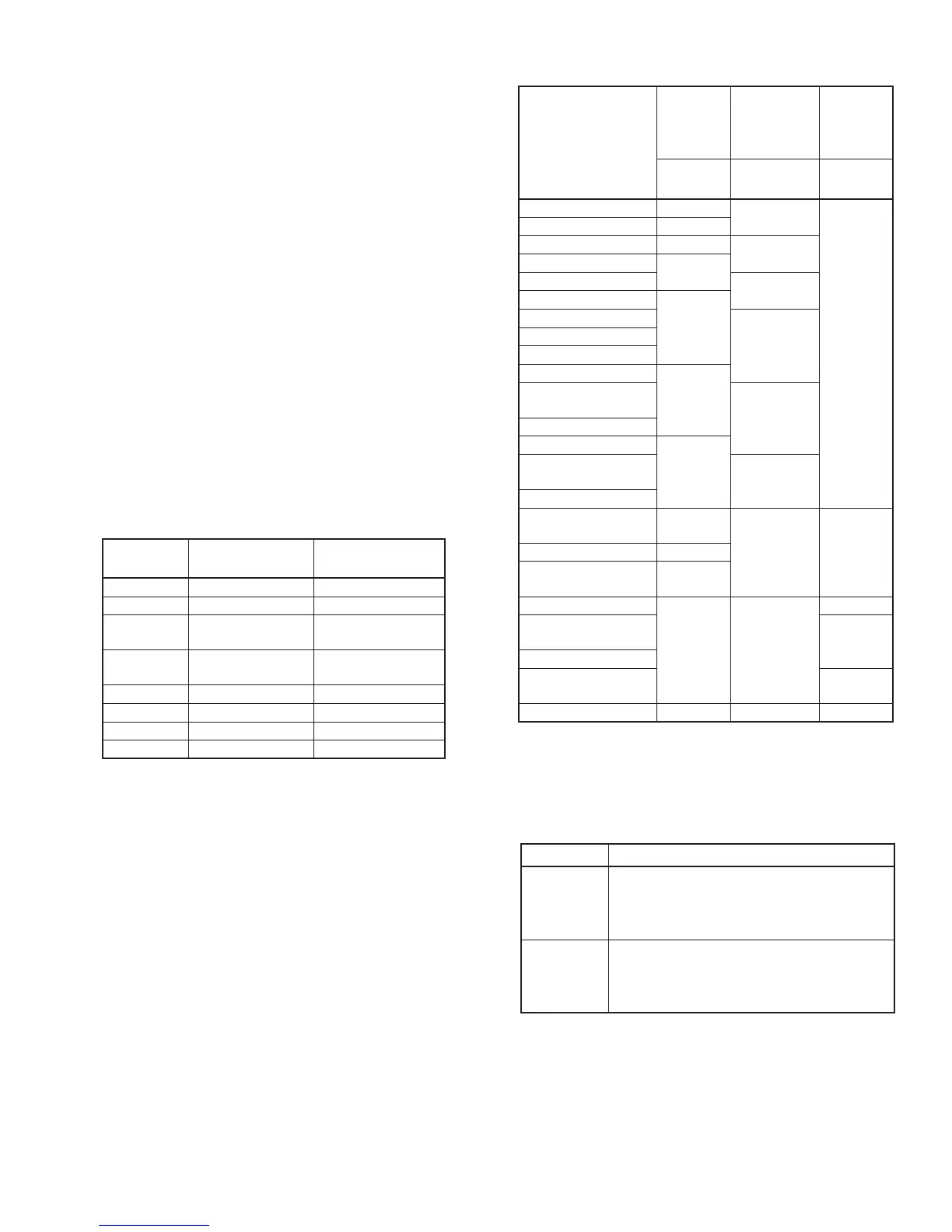
3-4-1 BAND SELECTION DATA
Frequency
[MHz]
IC2151
(MAIN)
IC2152
(MAIN)
IC2152
(MAIN)
IC981
(PA)
IC901
(DDS)
HPF
(MAIN)
LPF (PA)
LOF
(DDS)
0.03–1.599999 B0
L1
LOF1
1.6–1.999999 B1
2.0–3.399999 B2
L2
3.4–3.999999
B3
4.0–6.899999
L3
6.9–7.300000
B4
7.300001–7.999999
L4
8.0–10.999999
11.0–13.899999
13.9–14.350000
B5
14.350001–
14.999999
L5
15.0–20.899999
20.9–21.45
B6
21.450001–
21.999999
L6
22.0–29.999999
30.0–49.999999
T: B1
R: B7
L7 LOF250.0–54.0 B7
54.000001–
59.999999
T: B1
R: B7
60.0–115.512999
L8 L8
LOF3
115.513–
128.999999
LOF4
129.0-148.0
148.000001–
199.999999
LOF5
400.0–470.0 L9 L9 LOF6
3 - 8