SECTION 3 CIRCUIT DESCRIPTION
3 - 1
3-1 RECEIVER CIRCUITS
3-1-1 HF/50 MHz RF CIRCUIT (MAIN AND PA UNITS)
The HF/50 MHz RF filters pass only the desired band sig-
nals and suppress undesired band signals. The HF/50 MHz
RF circuit has 7 low-pass and 5 high-pass filters for speci-
fied band use.
The HF/50 MHz RF signals from the [ANT1] connector, pass
through one of 7 low-pass filters as below, the TX/RX switch
(PA unit; RL801), low-pass filter (PA unit; L801, L802, C801
–C805) and band switch (D151), and are then applied to the
MAIN unit via J101 (MAIN unit).
The signals from the PA unit are applied to the RF switch
(Q101) via the band switch (D113) and then passed through
the 20 dB attenuator (D101, D102).
The signals below 1.8 MHz are passed through the low-pass
filter (L103, L104, C106, C110, C111) and then applied to
the preamplifier circuit.
The other band signals (1.8–60 MHz) are passed through
the high-pass filter (L105, L109, L110, L116, L117, C108,
C109, C114–C116) to suppress strong signals below
1.8 MHz and then applied to the low-pass and high-pass fil-
ter circuits.
(1) 1.8–2 MHz
The filtered signals from the high-pass filter are passed
through the low-pass filter (L205, L207, C209–C213) and
then applied to the preamplifier circuits.
(2) 2–30 MHz
The filtered signals from the high-pass filter are applied to
one of 5 high-pass filters as at right above after passed
through the low-pass filter (L205, L207, C209–C213) and
are then applied to the preamplifier circuit.
(3) 30–60 MHz
The filtered signals from the high-pass filter are passed
through another high-pass filter (L215, L217, C228, C229,
C237, C238) and then amplified at the RF amplifier (Q211).
The amplified signals are applied to the preamplifier circuit.
3-1-2 VHF AND UHF RF CIRCUITS (PA UNIT)
The VHF and UHF RF circuits filter and amplify only the
desired band signals and suppress undesired band signals.
The both RF circuits have preamplifiers and bandpass filters.
• VHF RF CIRCUIT
The VHF RF signals from the [ANT2] connector pass
through the low-pass filters (L506, L508, L510, L601–L603,
C516, C519, C521, C601, C602) and antenna switching cir-
cuit (D507–D509). The switched signals are passed through
the attenuator (D551, D552) and bandpass filter (D553,
D554, D556). The filtered signals are applied to the pream-
plifier (Q551) and then passed through another bandpass
filter (D558–D560).
The filtered signals are passed through the band switch
(D462) and then applied to the 1st mixer circuit (MAIN unit)
via J101 (MAIN unit).
• UHF RF CIRCUIT
The UHF RF signals from the [ANT2] connector pass
through the low-pass (L601–L603, C601, C602) and high-
pass (L413, L414, C428, C429, C431, C433) filters and
then applied to the antenna switching circuit (D408–D410).
The switched signals are passed through the attenuator
(D451, D452) and then amplified at the preamplifier (Q451)
between the 2 bandpass filters (D453–D456). The filtered
signals are amplified at another preamplifier (IC471, pins 1, 4).
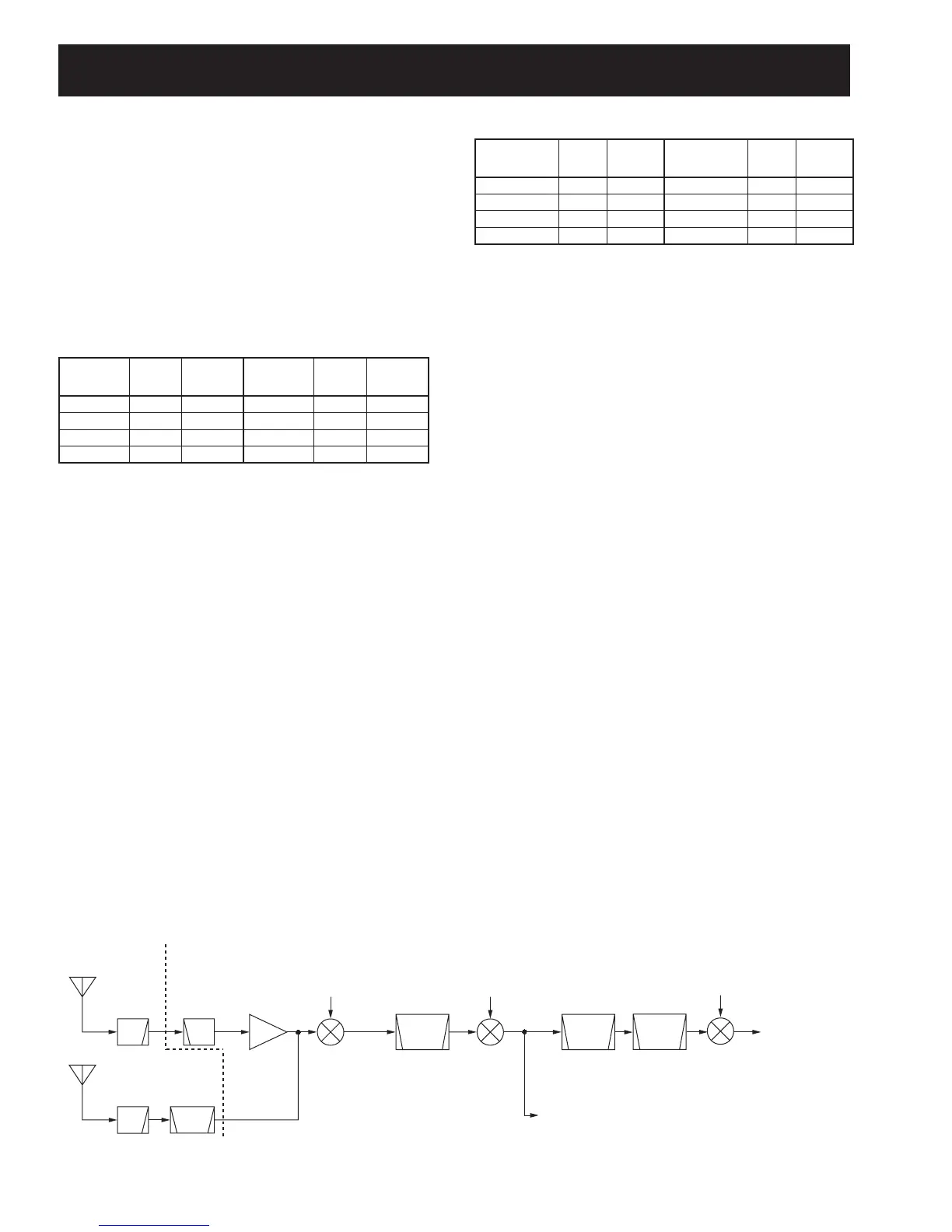
1st LO:
124.517 MHz–
594.587 MHz
BPF
LPF
HPF
1st mixer
IC401
2nd LO:
124.032 MHz
2nd mixer
D801
3rd mixer
IC1101
[ANT1]
0.03–60 MHz
LPF
[ANT2]
60–470 MHz
Crystal
filter
FI601
124.487 MHz
(WFM; 134.732 MHz)
Crystal
filter
FI901
to WFM detector
circuit (IC1401)
to DSP circuit
455 kHz
PA UNIT
MAIN UNIT
amp.
Preamp.
Q301
3rd LO:
438.85 kHz
Crystal
filter
FI1101
455 kHz
• Used RF low-pass fi lter (PA unit)
Frequency
(MHz)
Control
signal
Entrance
relay
Frequency
(MHz)
Control
signal
Entrance
relay
0.03–2 MHz L1 RL881 15–22 MHz L5 RL941
2–4 MHz L2 RL921 22–30 MHz L6 RL821
4–8 MHz L3 RL841 30–60 MHz L7 RL861
8–15 MHz L4 RL901
• Used RF high-pass fi lter (MAIN unit)
Frequency
(MHz)
Control
signal
Entrance
diode
Frequency
(MHz)
Control
signal
Entrance
diode
1.8–2 MHz B1 D204 13.9–20.9 MHz B5 D210
2–3.4 MHz B2 D205 20.9–30 MHz B6 D211
3.4–6.9 MHz B3 D208 30–60 MHz B7 D212
6.9–13.9 MHz B4 D209
• RECEIVER CONSTRUCTION