4 - 5
4-4 TRANSMITTER ADJUSTMENT (continue)
ADJUSTMENT ADJUSTMENT CONDITION
MEASUREMENT
VALUE
ADJUSTMENT
UNIT LOCATION UNIT ADJUST
SWR
DETECTOR
1 • Operating freq : 10.10000 MHz
• MODE : USB
• RF Power : 100%
• MIC Gain : 50%
• Connect an audio generator to
[MIC] connector and set as;
Frequency : 1.5 kHz
• Connect a wire between CP1601
(MAIN unit) and ground.
• Transmitting
REAR
panel
Connect an RF power
meter to [ANT1] connec-
tor.
80 W Audio
genera-
tor
Output
level
2 PA Connect a DC voltmeter
to CP961.
Minimum volt-
age
PA C964
After adjustment, disconnect the wire between CP1601 (MAIN unit) and ground.
TX PEAK 1 REAR
panel
Connect an RF power
meter to [ANT1] connec-
tor.
Maximum out-
put power
MAIN L701
• Operating freq. : 10.10000 MHz
• MODE : USB
• RF Power : 100%
• MIC Gain : 50%
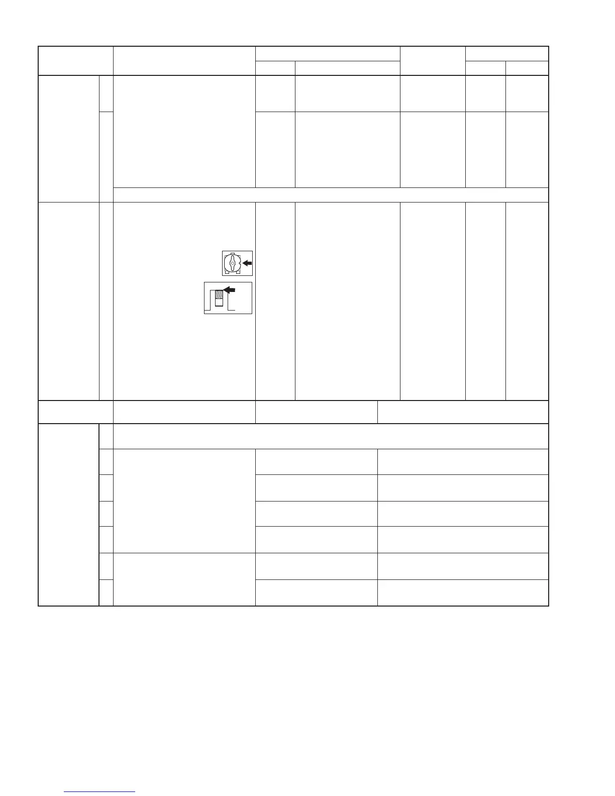
• Preset R1618 (MAIN
unit) as the illustration at
right.
• Preset L604, L612
and L904 (MAIN
unit) as the illustra-
tion at right.
• Connect an audio generator to
[MIC] connector and set as ;
Level : 1.5 kHz/3 mV
( Adjust the audio generator
output level to keep less than
50 W output power.)
• Transmitting
ADJUSTMENT ADJUSTMENT CONDITION DISPLAY OPERATION
TX TOTAL
GAIN
1 • Enter the adjustment mode.
• Push [F-2 (TX)].
2• Connect an RF power meter to
[ANT1] connector.
• Connect an audio generator to
[MIC] connector and set as;
Level : 1.5 kHz/3 mV
• Transmitting
TX Total Gain(HF1)
Set the output power to 50 W using
[DIAL]. Then push [F-4 (SET)].
3
TX Total Gain(HF2)
Set the output power to 50 W using
[DIAL]. Then push [F-4 (SET)].
4
TX Total Gain(HF3)
Set the output power to 50 W using
[DIAL]. Then push [F-4 (SET)].
5
TX Total Gain(50M)
Set the output power to 50 W using
[DIAL]. Then push [F-4 (SET)].
6• Connect an RF power to [ANT2]
connector.
• Transmitting
TX Total Gain(144M)
Set the output power to 25 W using
[DIAL]. Then push [F-4 (SET)].
7
TX Total Gain(430M)
Set the output power to 17.5 W using
[DIAL]. Then push [F-4 (SET)].
Core’s
top