3-3
3-2 RF UNIT (continued)
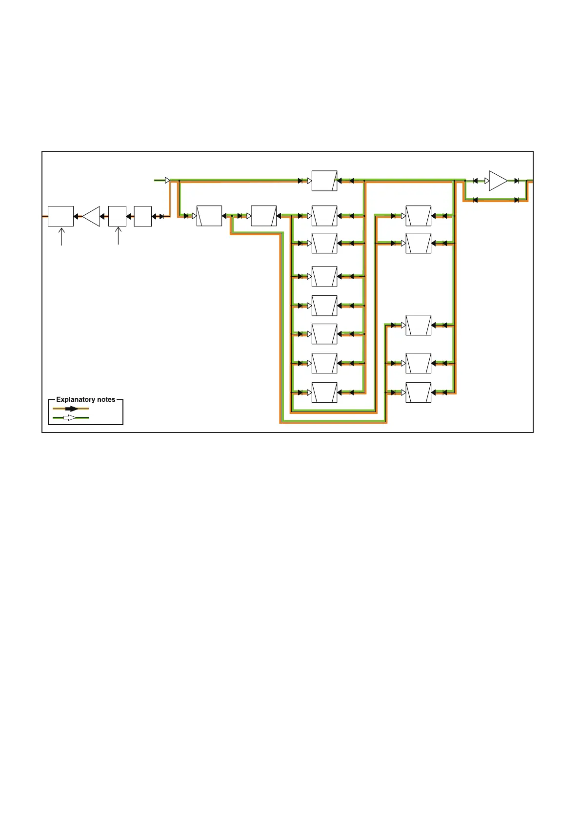
(2) TRANSMIT SIGNAL PROCESSING
The transmit signal from the MAIN UNIT is passed through
one of the BPFs in the filter circuit. The filtered signal level
is adjusted by the gain controller (D1051 and D1052), which
compensates the level difference in the band. The transmit
signal is then amplified by the YGR AMP (IC1031) to obtain
the input level needed in the transmit amplifier circuit.
PRE
AMP
Q1411
LPF
YGR
AMP
IC1031
RF
LPF
LPF
DRIVE
AMP
LPF
PWR
AMP
Q131
Q132
LPF
DRIVE
PRE
LPF
LPF
LPF
RF
AMP
D961,D962
PWR/SWR
DET
PIN
D1021
ATT
PIN
D1041
ATT
HPF
ATT
ALC
ALC
BPF
BPF
BPF
BPF
BPF
BPF
BPF
BPF
LPF
BPF
BPF
BPF
BPF
0.03-1.59 MHz
14.35-21.45 MHz
0.03-2.0 MHz
2.0-4.0 MHz
PA UNIT
21.45-33.0 MHz
33.0-76 MHz
Q111
7.3-14.35 MHz
Q121
4.0-7.3 MHz
Q101
1.60-74.80 MHz
D1051
D1052
22.00-29.99 MHz
50.00-54.00 MHz(TX)
30.00-49.99 MHz
54.01-69.99 MHz
70.00-72.00 MHz(TX)
15.00-21.99 MHz
2.00-2.99 MHz
4.50-6.49 MHz
10.00-14.99 MHz
3.00-4.49 MHz
8.00-9.99 MHz
6.50-7.99 MHz
1.60-30.00 MHz
AMOD
A/D
MIC
AMP
LPF
MICI
A/D
IC1001
RF UNIT
IC1003
IC1002
IC1002
D/A
IC1331
L1281,L1282
C1281,C1283,C1285
PIN
D1251
D1232
ATT
A/D
AMP BUFF
RF
J1302
1
2
3
4
5
6
7
8
9
10
11
12
13
LPF
LVDS
DRIVE
IC1212
BPF
XTAL
AMP
IC1221
MAIN UNIT
FPGA
IC1351
41.344 MHz
(41.344 MHz)
Q1202
Q1201
DACLK
X1201
IC1211
5.BAND
10.FSKK
3.HSEND
13.SQLS
4.START
7.NC
11.MOD
1.8V
2.GND
9.KEY
6.ALC
[ACC]
12.AF
8.14V
124.032 MHz
/FPCAL/BCLK/FRM/MCLK
FPX_AGC/FPX_DET/FPR_MOD
J1
1
2
3
4
5
6
7
8
DISPLAY UNIT
GND
MIC U/D
MIC
+8V
SQL
PTT
MICE
MIC UNIT
AF OUT
PHASEI
PHASE
DET
SWR
DET
SWRL
ATT
IMPI
SW11
SW11
TPWRL
BUFF
D1505
IMP
DET
D1271
TUNE
NET
TUNER UNIT
IC1701
HF/
50 MHz/
70 MHz
D1311 D1312
IC1701
POWER
DET
D1201
IC1901
IF-DSP
IC901
• RF UNIT (Transmit circuits)
The signal level is also adjusted by the ALC circuit (D1201
and D1041), which is located at the input and output of YGR
AMP (IC1031). The ALC circuit automatically adjusts the
transmit signal level according to the transmit power sensing
voltage. The level-adjusted transmit signal is then applied to
the PA UNIT.
TX signal
RX signal

 Loading...


