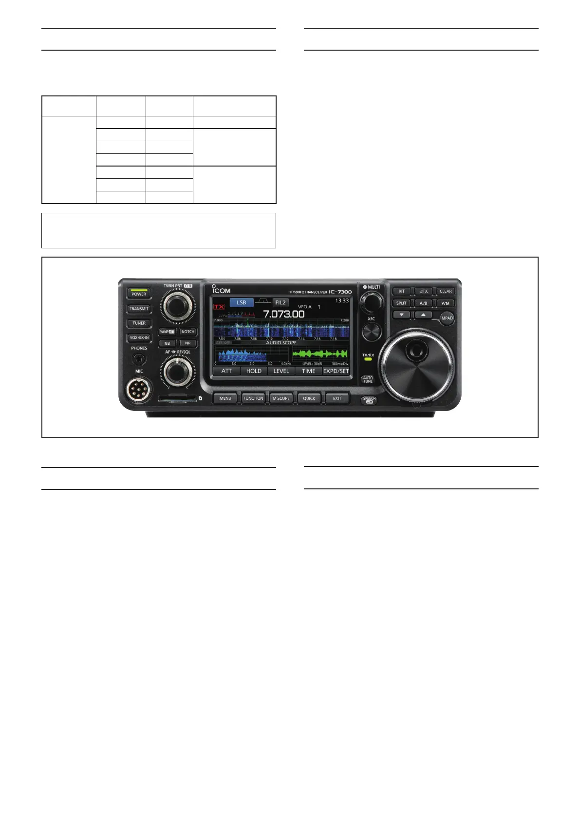
This service manual describes the latest technical informa-
tion for the IC-7300
HF/50 MHz transceiver, at the time of pub-
lication.
NEVER connect the transceiver to a DC power supply that
uses more than the specified voltage. This will ruin the trans-
ceiver.
DO NOT expose the transceiver to rain, snow or liquids.
DO NOT reverse the polarities of the power supply when di-
rectly applying power to the transceiver/circuit.
DO NOT apply an RF signal of more than 20 dBm (100 mW) to
the antenna connector. This could damage the transceiver’s
front-end.
To upgrade quality, any electrical or mechanical parts
and internal circuits are subject to change without notice
or obligation.
Be sure to include the following four points when ordering
replacement parts:
1. 10-digit Icom part number
2. Component name
3. Equipment model name and unit name
4. Quantity required
<ORDER EXAMPLE>
1180004830 XC6222A331MR IC-7300 MAIN UNIT 5 pieces
8110010940 3765 U-COVER IC-7300 CHASSIS 1 piece
Addresses are provided on the inside back cover for your
convenience.
ORDERING PARTS
1. Make sure that the problem is internal before disassem-
bling the transceiver.
2. DO NOT open the transceiver until the transceiver is dis-
connected from its power source.
3. DO NOT force any of the variable components. Turn them
slowly and smoothly.
4. DO NOT short any circuits or electronic parts. An insulated
tuning tool MUST be used for all adjustments.
5. DO NOT keep power ON for a long time when the trans-
ceiver is defective.
6. NEVER directly transmit power into any test equipment
such as Standard Signal Generator or a Sweep Generator,
otherwise the RF power may damage them.
7. ALWAYS connect a 50 dB to 60 dB attenuator between the
transceiver and such test equipment.
8. READ the instructions of the test equipment thoroughly
before connecting it to the transceiver.
REPAIR NOTES
INTRODUCTION SERVICE CAUTION
Icom, Icom Inc. and the Icom logo are registered trademarks of Icom Incorporated (Japan) in Japan, the United States, the
United Kingdom, Germany, France, Spain, Russia, Australia, New Zealand, and/or other countries.
MODEL VERSION
VERSION
NUMBER
OPERATABLE
BANDS
IC-7300
USA #02 HF/50 MHz
EUR #03 HF/50/70 MHz
ITR #05
ESP #06
TPE #07 HF/50 MHz
KOR #08
EXP #12
 Loading...


