LSB
MD
3.8 _5
LI. LI
n n
VFO A
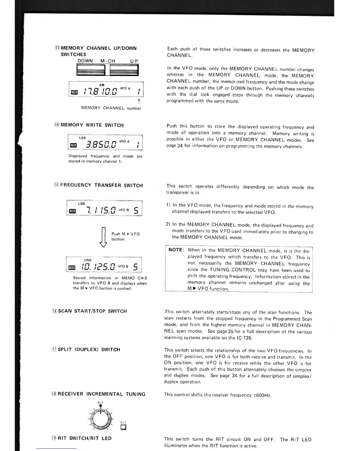
13 MEMORY CHANNEL UP/DOWN
SWITCHES
DOWN M - CH
U P
AM
n
n
VFO A
CE3
t 1.1 t
LI.
LI
MEMORY CHANNEL number
MEMORY WRITE SWITCH
Displayed frequency and mode are
stored in memory channel 1.
LSB
11
n
VFO B
I.
I 1_1.11
5
0 FREQUENCY TRANSFER SWITCH
Push M
►
VFO
button.
Stored information in MEMO CH-5
transfers to VFO B and displays when
the M
►
VFO button is pushed.
USB
can10
.
05.l7
VFO B 5
NOTE:
When in the MEMORY CHANNEL mode, it is the dis-
played frequency which transfers to the VFO. This is
not necessarily the MEMORY CHANNEL frequency
since the TUNING CONTROL may have been used to
shift the operating frequency. Information stored in the
memory channel remains unchanged after using the
M
►
VFO function.
Each push of these switches increases or decreases the MEMORY
CHANNEL.
In the VFO mode, only the MEMORY CHANNEL number changes
whereas in the MEMORY CHANNEL mode, the MEMORY
CHANNEL number, the memorized frequency and the mode change
with each push of the UP or DOWN button. Pushing these switches
with the dial lock engaged steps through the memory channels
programmed with the same mode.
Push this button to store the displayed operating frequency and
mode of operation into a memory channel. Memory writing is
possible in either the VFO or MEMORY CHANNEL modes. See
page 34 for information on programming the memory channels.
This switch operates differently depending on which mode the
transceiver is in.
1)
In the V FO mode, the frequency and mode stored in the memory
channel displayed transfers to the selected VFO.
2)
In the MEMORY CHANNEL mode, the displayed frequency and
mode transfers to the VFO used immediately prior to changing to
the MEMORY CHANNEL mode.
ED
SCAN START/STOP SWITCH
©SPLIT (DUPLEX) SWITCH
0 RECEIVER INCREMENTAL TUNING
RIT
This switch alternately starts/stops any of the scan functions. The
scan restarts from the stopped frequency in the Programmed Scan
mode, and from the highest memory channel in MEMORY CHAN-
NEL scan modes. See page 35 for a full description of the various
scanning systems available on the IC-735.
This switch selects the relationship of the two VFO frequencies. In
the OFF position, one VFO is for both receive and transmit. In the
ON position, one VFO is for receive while the other VFO is for
transmit. Each push of this button alternately chooses the simplex
and duplex modes. See page 34 for a full description of simplex/
duplex operation.
This control shifts the receiver frequency ±800Hz.
RIT
a
RIT SWITCH/RIT LED
This switch turns the RIT circuit ON and OFF. The RIT LED
illuminates when the RIT function is active.

 Loading...


