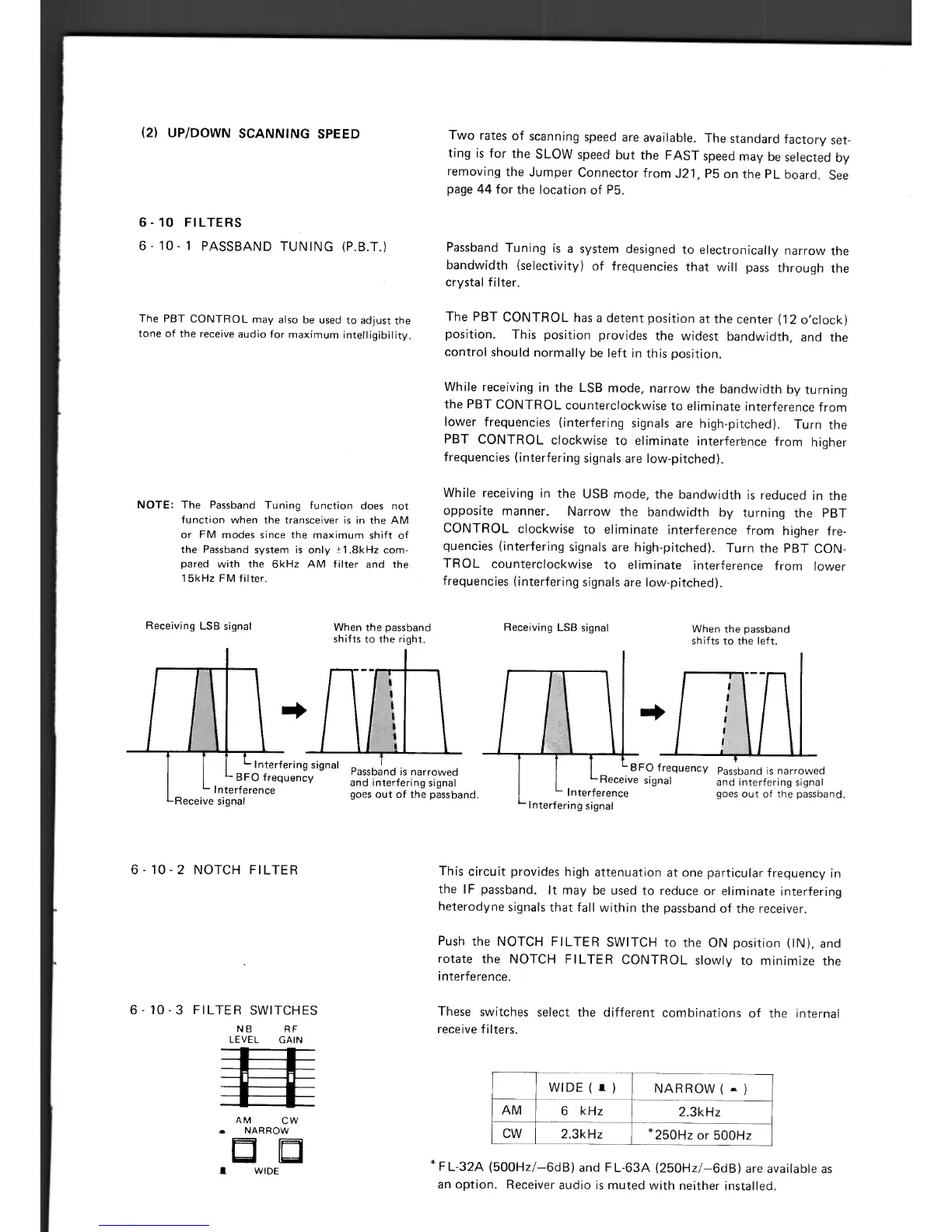
Receiving LSB signal
When the passband
shifts to the left.
and interfering signal
Interference goes out of the passband.
Interfering signal
tRe
—B
F
O
signal
O frequency Passband is narrowed
(2) UP/DOWN SCANNING SPEED
Two rates of scanning speed are available. The standard factory set-
ting is for the SLOW speed but the FAST speed may be selected by
removing the Jumper Connector from J21, P5 on the PL board. See
page 44 for the location of P5.
6-10 FILTERS
6 - 10 - 1 PASSBAND TUNING (P.B.T.)
The PBT CONTROL may also be used to adjust the
tone of the receive audio for maximum intelligibility.
NOTE:
The Passband Tuning function does not
function when the transceiver is in the AM
or FM modes since the maximum shift of
the Passband system is only ±1.8kHz com-
pared with the 6kHz AM filter and the
15kHz FM filter.
Receiving LSB signal
When the passband
shifts to the right.
[[
L
Interfering signal
— B FO frequency
Interference
Receive signal
Passband Tuning is a system designed to electronically narrow the
bandwidth (selectivity) of frequencies that will pass through the
crystal filter.
The PBT CONTROL has a detent position at the center (12 o'clock)
position. This position provides the widest bandwidth, and the
control should normally be left in this position.
While receiving in the LSB mode, narrow the bandwidth by turning
the PBT CONTROL counterclockwise to eliminate interference from
lower frequencies (interfering signals are high-pitched). Turn the
PBT CONTROL clockwise to eliminate interferbnce from higher
frequencies (interfering signals are low-pitched).
While receiving in the USB mode, the bandwidth is reduced in the
opposite manner. Narrow the bandwidth by turning the PBT
CONTROL clockwise to eliminate interference from higher fre-
quencies (interfering signals are high-pitched). Turn the PBT CON-
TROL counterclockwise to eliminate interference from lower
frequencies (interfering signals are low-pitched).
I I I
Passband is narrowed
and interfering signal
goes out of the passband.
6 - 10 - 2 NOTCH FILTER
6 - 10 - 3 FILTER SWITCHES
NB
RF
LEVEL
GAIN
AM
CW
NARROW
D
WIDE
This circuit provides high attenuation at one particular frequency in
the IF passband. It may be used to reduce or eliminate interfering
heterodyne signals that fall within the passband of the receiver.
Push the NOTCH FILTER SWITCH to the ON position (IN), and
rotate the NOTCH FILTER CONTROL slowly to minimize the
interference.
These switches select the different combinations of the internal
receive filters.
WIDE (
. )
NARROW ( —
AM
6
kHz
2.3kHz
CW
2.3kHz
*
250Hz or 500Hz
*
FL-32A 500Hz/-6dB) and FL-63A (250Hz/-6dB) are available as
an option. Receiver audio is muted with neither installed.

 Loading...


