XMIT
RECV
AGC (AUTOMATIC GAIN CONTROL)
SWITCH
CD COMP (SPEECH COMPRESSOR) SWITCH
3 - 2 FREQUENCY DISPLAY
This switch changes the time constant of the AGC circuit. When the
switch is OUT, the AGC voltage reduces slowly for SSB reception.
When the switch is IN, the AGC voltage reduces quickly for either
CW reception or for receiving signals with rapid fading.
This switch turns the speech compressor circuit ON and OFF. The
circuit provides greater talk power by improving the intelligibility of
the transmitted signal over long distances.
The frequency of the IC-735 is displayed on a liquid-crystal display
(LCD). The display indicates the carrier frequency using both MHz
and kHz decimal points when in any mode (USB, LSB, CW, AM,
FM).
Remember, the displayed frequency does not change when using the
R IT function (explained later), although the actual receive fre-
quency does change.
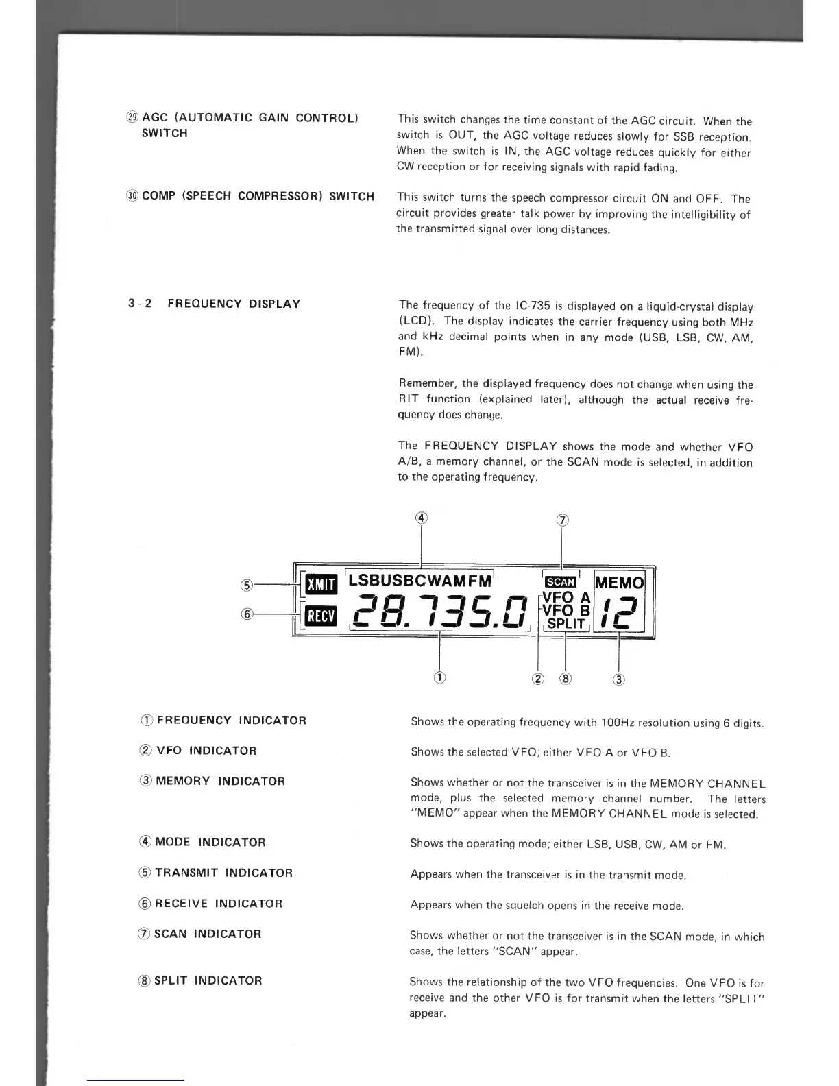
The FREQUENCY DISPLAY shows the mode and whether VFO
A/B, a memory channel, or the SCAN mode is selected, in addition
to the operating frequency.
O
LSBUSBCWAM FM'
PR
35
n
t_.
t,
I
I
SCAN
VFO A
VFO B
I
SPLIT
MEMO
j
IL
O
c,
FREQUENCY INDICATOR
VFO INDICATOR
MEMORY INDICATOR
® MODE INDICATOR
® TRANSMIT INDICATOR
® RECEIVE INDICATOR
(I)
SCAN INDICATOR
Shows the operating frequency with 100Hz resolution using 6 digits.
Shows the selected VFO; either
VFO A or VFO B.
Shows whether or not the transceiver is in the MEMORY CHANNEL
mode, plus the selected memory channel number. The letters
"MEMO" appear when the MEMORY CHANNEL mode is selected.
Shows the operating mode; either LSB, USB, CW, AM or FM.
Appears when the transceiver is in the transmit mode.
Appears when the squelch opens in the receive mode.
Shows whether or not the transceiver is in the SCAN mode, in which
case, the letters "SCAN" appear.
® SPLIT INDICATOR
Shows the relationship of the two VFO frequencies. One VFO is for
receive and the other VFO is for transmit when the letters "SPLIT"
appear.