OO
FILTER SWITCHES
AM
CW
NARROW
These switches select the different combinations of the second IF
(9MHz) filter and the third IF(455kHz) filter to improve the receiver
selectivity. These filters function in conjunction with the Passband
Tuning system. See page 31 and 38 for more information.
I
WIDE
© METER SWITCH
This switch selects the meter function when in the transmit mode as
follows:
(1)
ALC: The meter indicates the ALC level. The meter begins to
give an indication when the RF power reaches a certain
value.
(2)
PO:
The meter indicates the relative RF output power.
NOTE:
The meter switch on the rear panel of the transceiver
should be in the PO position in order for the PO meter
reading to be accurate.
CD
VOX SWITCH
CW BREAK-IN SWITCH
g
E LEC-KEY/MANUAL SWITCH
This switch turns the VOX circuit ON and OFF. The automatic T/R
switching VOX circuit functions in the PHONE and CW modes when
the switch is IN. In CW, semi break-in or full break-in operation is
possible.
Push this switch IN for full break-in CW operation and OUT for semi
break-in operation. The VOX SWITCH must also be IN for the
BREAK-IN SWITCH to operate. See page 31 for more information.
When an optional ELECTRONIC KEYER UNIT is installed, push
this switch IN to activate the automatic, iambic keyer, and connect a
keyer paddle to the KEY jack on the rear panel of the transceiver.
See page 32 for more information on the use of the keyer. The unit
installation is described on page 23.
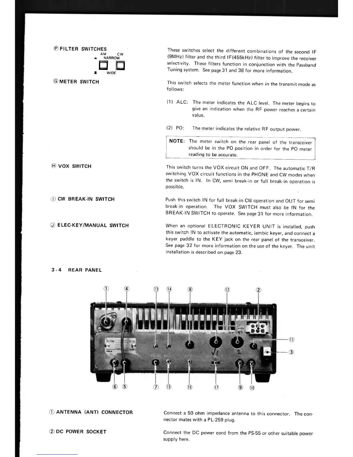
3 - 4 REAR PANEL
0
ANTENNA (ANT) CONNECTOR
Connect a 50 ohm impedance antenna to this connector. The con-
nector mates with a PL-259 plug.
cp
DC POWER SOCKET
Connect the DC power cord from the PS-55 or other suitable power
supply here.