AT-150
IC-735
.R1*
0
°O.. 40 °00
000°
0000
.00
0
0 0
®
0 0 o
0
0 0
= O
©
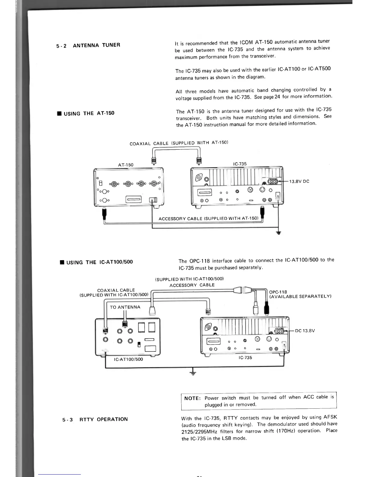
ACCESSORY CABLE (SUPPLIED WITH AT-150)
(
I
00
COAXIAL CABLE
(SUPPLIED WITH IC-AT100/500)
OPC-118
(AVAILABLE SEPARATELY)
101 o o
p
0
0 O
O11
=
I
I
n
USING THE IC-AT100/500
The OPC-118 interface cable to connect the IC-AT100/500 to the
IC-735 must be purchased separately.
(SUPPLIED WITH IC-AT100/500)
ACCESSORY CABLE
TO ANTENNA
0
0
DC 13.8V
1..1
o o 0 0 0 0
00 C)
o
0
o
0
0
5 - 2 ANTENNA TUNER
n
USING THE AT-150
It is recommended that the ICOM AT-150 automatic antenna tuner
be used between the IC-735 and the antenna system to achieve
maximum performance from the transceiver.
The IC-735 may also be used with the earlier IC-AT100 or IC-AT500
antenna tuners as shown in the diagram.
All three models have automatic band changing controlled by a
voltage supplied from the IC-735. See page 24 for more information.
The AT-150 is the antenna tuner designed for use with the IC-735
transceiver. Both units have matching styles and dimensions. See
the AT-150 instruction manual for more detailed information.
COAXIAL CABLE (SUPPLIED WITH AT-150)
13.8V DC
I C-AT100/500
IC-735
_L
NOTE:
Power switch must be turned off when ACC cable is
plugged in or removed.
5
-
3 RTTY OPERATION
With the IC-735, RTTY contacts may be enjoyed by using AFSK
(audio frequency shift keying). The demodulator used should have
2125/2295MHz filters for narrow shift (170Hz) operation. Place
the IC-735 in the LSB mode.
At A