SECTION
4
INSTALLATION
4
-
1
PLANNING
Select a
location
for your transceiver which allows
free
access to the
front panel controls,
good
air circulation
and rear clearance for
access to
the rear panel connections.
• PRECAUTIONS
4-2
MOUNTING
THE
TRANSCEIVER
4-3
ANTENNA
•
Mobile or
marine
installations:
An optional IC-MB18 mounting bracket is available to mount your
IC-751A. Select
a
location
which can
support the weight of the
unit, and which
does
not
interfere with the
normal
operation of
the vehicle or
boat.
Provide
protection
from direct
rain
on boats.
“
Avoid
using the IC-751
A
in the
following
situations:
1)
Where temperatures under
—
10°C or
over +60°C are encountered.
For
example, DO NOT use the IC-751 A in areas
exposed
to
direct
sunlight or near heat-producing devices such as heaters or ranges.
2)
In humid
or
moist places including bathrooms.
DO NOT run the antenna feedline near electronic instruments or
magnetic compasses.
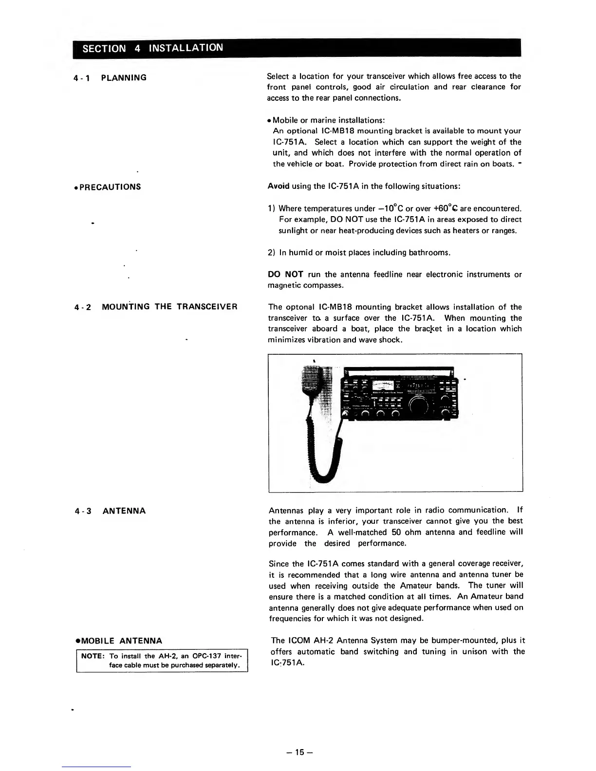
The
optonal
IC-MB18 mounting
bracket allows installation of the
transceiver
ta
a
surface
over
the IC-751 A. When mounting the
transceiver aboard
a
boat, place the bracket in
a
location which
minimizes vibration
and wave
shock.
Antennas play a
very
important role in
radio
communication.
If
the antenna is
inferior,
your
transceiver cannot
give
you
the best
performance. A
well-matched 50
ohm
antenna
and
feedline
will
provide the
desired
performance.
Since the
IC-751
A comes standard with a
general coverage
receiver,
it is
recommended
that a long
wire antenna
and antenna
tuner be
used when
receiving outside
the
Amateur bands.
The
tuner will
ensure there is a
matched condition at
all times.
An Amateur
band
antenna generally does
not
give adequate
performance
when used on
frequencies
for which it
was not designed.
•
MOBILE ANTENNA
NOTE: To install the
AH-2,
an
OPC-137 inter-
face cable must be
purchased separately.
The I COM
AH-2 Antenna System may be
bumper-mounted, plus
it
offers
automatic band switching
and tuning in unison with the
IC:751A.
-
15
-