7-12 MICROPHONE
UP/DOWN
OPERATION
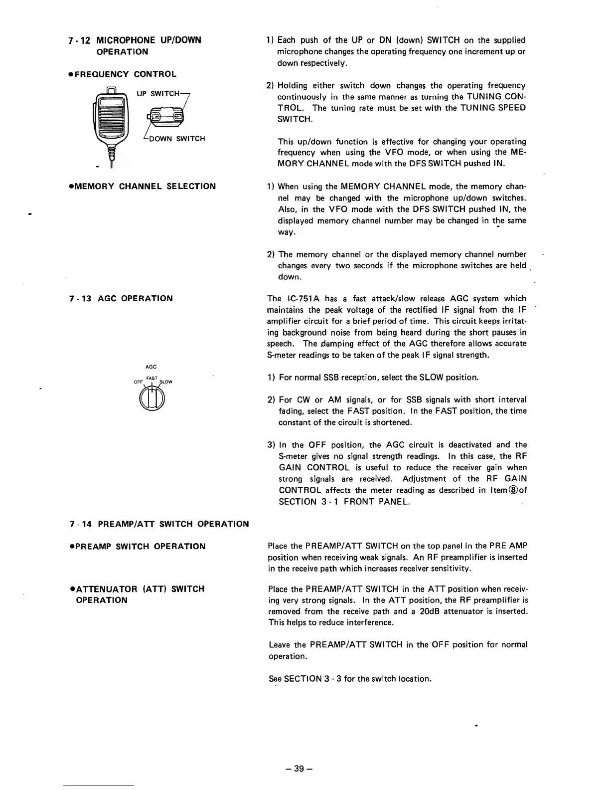
•FREQUENCY
CONTROL
•MEMORY CHANNEL SELECTION
7
-13
AGC
OPERATION
AGO
1)
Each push of the
UP
or DN
(down) SWITCH on the supplied
microphone changes the operating frequency
one
increment up or
down respectively.
2)
Holding
either switch down changes the
operating
frequency
continuously in the same manner
as
turning the
TUNING CON-
TROL. The tuning rate must be set
with the TUNING
SPEED
SWITCH.
This up/down function
is
effective for
changing your operating
frequency when
using
the
VFO mode, or
when using the
ME-
MORY CHANNEL mode with the DFS
SWITCH pushed
IN.
1)
When using the MEMORY
CHANNEL
mode,
the memory
chan-
nel may be changed with
the microphone up/down
switches.
Also,
In the
VFO
mode with
the DFS SWITCH
pushed IN,
the
displayed memory
channel number may be changed in
the same
way.
2)
The memory channel or the
displayed memory channel
number
changes
every
two
seconds If the microphone
switches are held
down.
The
IC-751A has
a
fast
attack/slow release AGC system
which
maintains the peak
voltage of the rectified IF
signal
from the
IF
amplifier circuit for
a
brief period of time. This circuit keeps
irritat-
ing background
noise
from being heard during the short
pauses in
speech. The damping
effect of the AGC therefore allows
accurate
S-meter
readings to be
taken of the peak IF signal strength.
1
)
For
normal SSB
reception, select the
SLOW
position.
2)
For CW or AM
signals, or for
SSB
signals
with
short
interval
fading,
select
the FAST position. In the FAST
position, the time
constant of the circuit is shortened.
3)
In the OFF position, the
AGC circuit
is
deactivated and
the
S-meter gives no signal strength
readings.
In
this case, the RF
GAIN
CONTROL is useful
to
reduce the
receiver
gain
when
strong signals are
received.
Adjustment
of the RF
GAIN
CONTROL affects the
meter reading
as
described in
ltem(Dof
SECTION
3-1
FRONT PANEL.
7
-14
PREAMP/ATT SWITCH
OPERATION
•PREAMP
SWITCH
OPERATION
Place the
PREAMP/
ATT
SWITCH
on the top
panel in the
PRE AMP
position when
receiving weak signals. An
RF preamplifier is
inserted
in the receive path
which Increases receiver sensitivity.
•ATTENUATOR
(ATT)
SWITCH
Place the
PREAMP/
ATT
SWITCH in the ATT position
when receiv-
OPERATION ing very strong
signals. In
the
ATT position, the
RF preamplifier
is
removed from the receive path and
a
20dB attenuator is
inserted.
This helps
to
reduce interference.
Leave
the
PREAMP/ATT SWITCH in the
OFF
position
for normal
operation.
See SECTION
3
-
3 for the switch location.
-
39
-