10
-3
IC-EX310 VOICE SYNTHESIZER
UNIT
After
being installed, the voice synthesizer
announces
the
displayed
frequency when the SPEECH
SWITCH on the front panel
is
pushed.
•
INSTALLATION
1
)
Turn
the transceiver upside down.
2)
Install the IC-EX310 unit
as
shown
in
the photo using the four
supplied screws.
Insert the
2-pin plug
shown in the photo into
J2 of
the IC-EX310ui^it.
3)
Plug
the 8-pin plug from
the IC-EX310 into J12 on the LOGIC
unit.
4)
Adjust the volume
and speech speed if necessary. The procedure
is described
below.
5)
Replace the
top
and bottom covers on the IC-751
A.
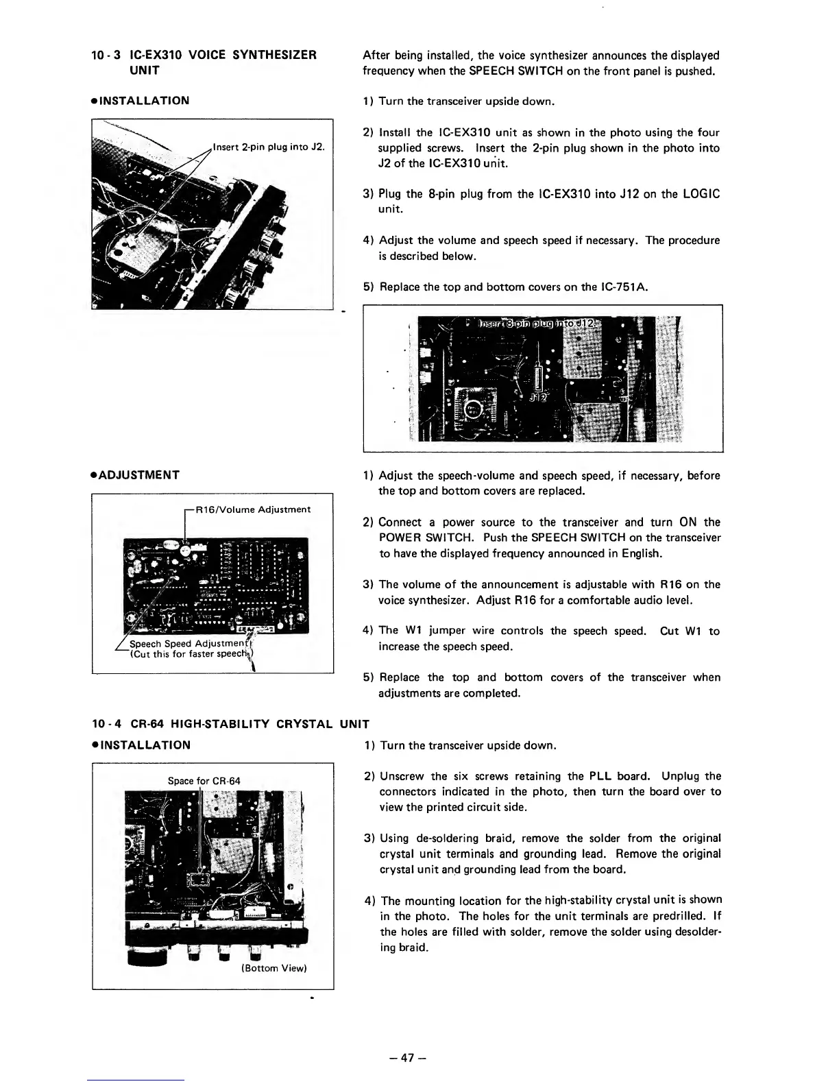
•ADJUSTMENT
1)
Adjust
the
speech-volume and
speech
speed,
if necessary,
before
the
top
and bottom covers are
replaced.
2)
Connect
a
power
source to the transceiver and turn ON
the
POWER
SWITCH.
Push the SPEECH SWITCH on the
transceiver
to
have the displayed frequency announced in English.
3)
The volume of the announcement is adjustable with R16 on the
voice synthesizer.
Adjust R16 for a comfortable audio
level.
4)
The W1 jumper
wire
controls
the
speech
speed. Cut
W1 to
increase the speech
speed.
5)
Replace the
top
and bottom covers of the transceiver when
adjustments are completed.
10-4
CR-64 HIGH-STABILITY CRYSTAL
UNIT
•
INSTALLATION
1
)
Turn the transceiver upside
down.
2)
Unscrew the six screws retaining the
PLL
board.
Unplug the
connectors
indicated in the
photo, then turn the board over to
view the printed circuit
side.
3)
Using de-soldering braid,
remove
the solder
from the original
crystal unit terminals and grounding lead. Remove
the original
crystal unit and grounding
lead
from the board.
4)
The mounting location
for the
high-stability
crystal
unit
is
shown
in the photo. The holes for the unit terminals
are predrilled.
If
the holes are filled with solder, remove the solder using
desolder-
ing braid.
-47
-