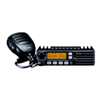
q ANTENNA CONNECTOR
Connects to an antenna. Contact your dealer about an-
tenna selection and placement.
w MICROPHONE HANGER
Connect the supplied microphone hanger to the vehicle’s
ground for microphone on/off hook functions. (See p. 2)
e DC POWER RECEPTACLE
Connects to a
12 V DC battery. Pay attention to polarities.
R WARNING! NEVER connect to a 24 V battery. This
could damage the transceiver.
r OPTIONAL CABLE (OPC-617)
Connect an external modem unit, dimmer control, etc.
t EXTERNAL SPEAKER JACK
Connect a 4–8
ø external speaker, if desired.
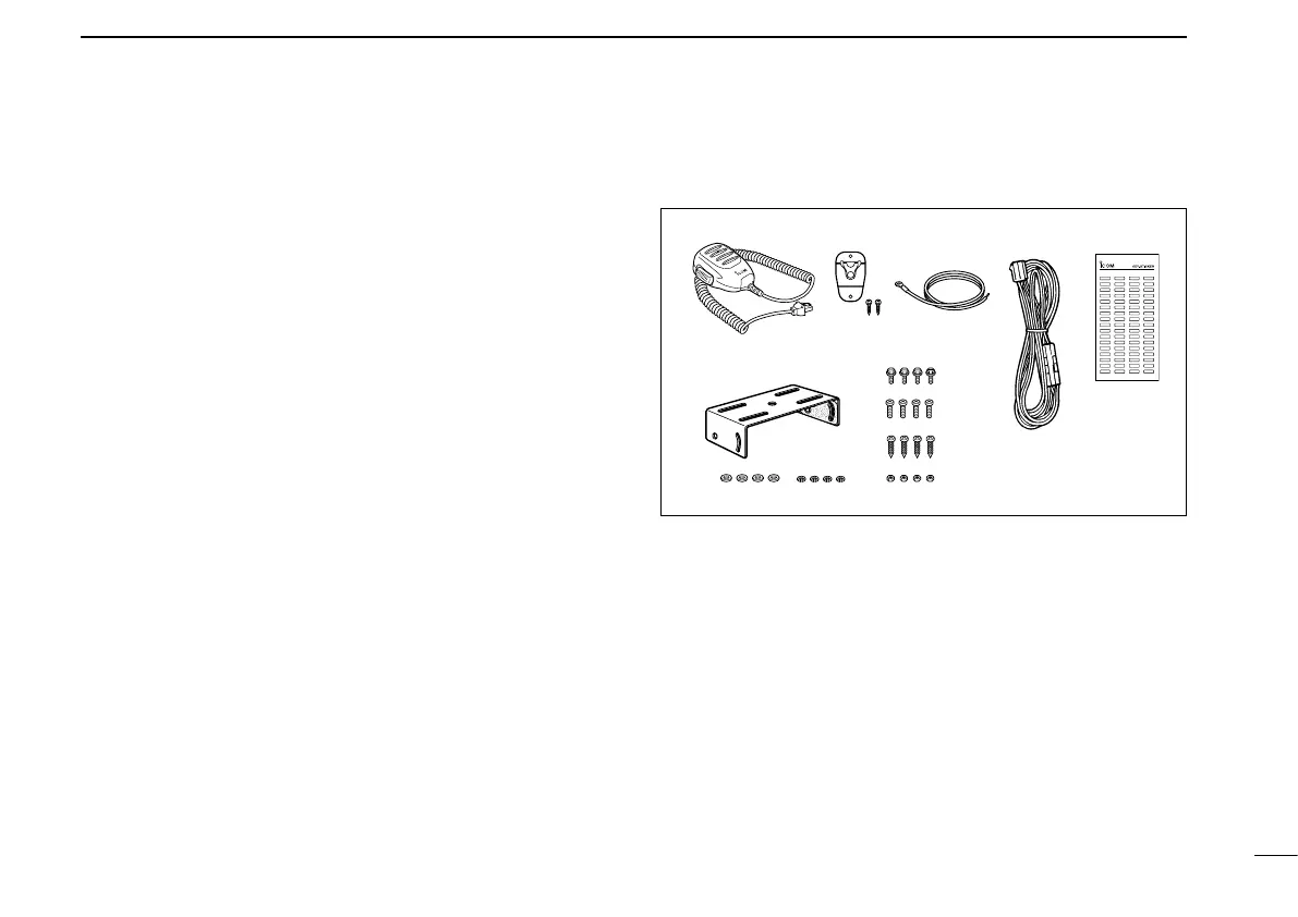
■ Supplied Accessories
q Microphone ...................... 1
w Microphone hanger and
screw set ..................... 1 set
e
Microphone hanger cable
... 1
r DC power cable (OPC-1132)
............................................1
t Function name stickers*
(KEY STICKER) ....................1
y Mounting bracket ............... 1
u Bracket bolts ..................... 4
i Mounting screws (M5×12) ...4
o Self-tapping screws (M5×20)
........................................... 4
!0 Flat washers ...................... 4
!1 Spring washers ................. 4
!2 Nuts ................................... 4
*Function name stickers
There are no names on the programmable function keys since the
functions can be freely assigned to these keys.
Attach the supplied function name stickers above the appropriate
keys for easy recognition of that key’s assigned function.
12
3
CONNECTION AND MAINTENANCE
 Loading...