July 2016
(Amended page)
6-5 FREQUENCY ADJUSTMENT
(For [#07], [#14], [#15], [#16], [#23], [#35], [#36], [#37] and [#82])
1) Select an adjustment item using cursor or [
] / [
] keys of the PC’s keyboard.
2) Set or modify the adjustment value as specifi ed using [
] / [
] keys of the PC’s keyboard, then push the [ENTER] key.
ADJUSTMENT
ADJUSTMENT CONDI-
TION
OPERATION
ADJUST-
MENT
ITEM
VALUE
PLL LOCK
VOLTAGE
1
–
1) Connect an RF power meter to the
TX antenna.
2) Set the preset adjustment value on
the adjustment utility window.
[LV (RX L)] 169 [3.31 V]
[LV (RX H)] 161 [3.15 V]
[LV (TX L)] 191 [3.74 V]
[LV (TX H)] 161 [3.15 V]
RX
(Band center)
2 • Channel: 1-1
• Receiving
• Select the item [RX LVA L], then
push the [ENTER] key.
[RX LVA L]
(Automatic
adjustment)
RX
(Band high)
3 • Channel: 1-2
• Receiving
•
Select the item [RX LVA H], then
push the [ENTER] key.
[RX LVA H]
TX
(Band low)
4 • Channel: 1-3
• Transmitting
• Select the item [TX LVA L], then push
the [ENTER] key.
[TX LVA L]
TX
(Band center)
5 • Channel: 1-4
• Transmitting
• Select the item [TX LVA H], then
push the [ENTER] key.
[TX LVA H]
LOCK
VOLTAGE
VERIFY
RX
(Band low)
1 • Channel: 1-5
• Receiving
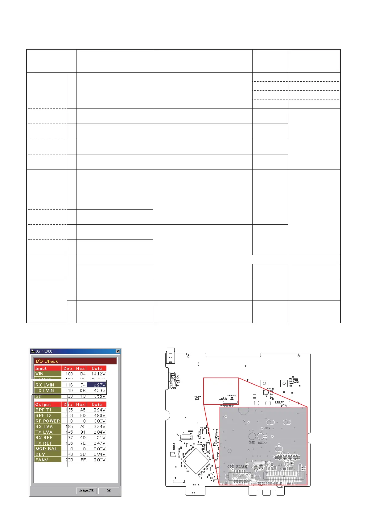
• Verify the lock voltage at each chan-
nels on the [RX LIVIN] item on the
"I/O Check window" as below.
[RX LIVIN]
(I/O Check
window)
0.5–2.0 V
(Verify)
RX
(Band center)
2 • Channel: 1-6
• Receiving
TX
(Band low)
3 • Channel: 1-7
• Transmitting
• Verify the lock voltage at each chan-
nels on the [TX LIVIN] item on the
"I/O Check window" on the MAIN/-A
UNIT as below.
[TX LIVIN]
(I/O Check
window)
TX
(Band high)
4 • Channel: 1-8
• Transmitting
RX
FREQUENCY
VERIFY
1 NOTE: Only when the RX frequency is not in the specifi ed range, re-adjust the RX frequency.
• Channel: 1-8
• Receiving
• Connect an frequency counter to the
1st LO check point as below.
[RX REF]
220.2500 MHz (1st LO)
(
±50 Hz)
TX
FREQUENCY
1
–
1) Set the item [TX Mode] to "1."
2) Connect an RF power meter to the
TX antenna.
[TX Mode]
"1"
(Analog Voice)
2 • Channel: 1-9
• Transmitting
1) Adjust the frequency using [
] / [
]
keys of the PC’s keyboard.
2) Push [ENTER] to store the value.
[TX REF]
173.9000 MHz
(
±50 Hz)
6-8
DSUB
CPU FLASH
RXLO
GND
• I/O CHECK WINDOW • 1ST LO CHECK POINT
(MAIN/-A UNIT)
Lock voltage verify

 Loading...


