July 2016
(Amended page)
6-6 TRANSMIT ADJUSTMENT
(For [#07], [#14], [#15], [#16], [#23], [#35], [#36], [#37] and [#82])
1) Select an adjustment item using cursor or [
] / [
] keys of the PC’s keyboard.
2) Set or modify the adjustment value as specifi ed using [
] / [
] keys of the PC’s keyboard, then push the [ENTER] key.
ADJUSTMENT
ADJUSTMENT CONDI-
TION
OPERATION
ADJUST-
MENT
ITEM
VALUE
TX
Output Power
-Preparation-
1
–
• Connect the RF power meter to the
TX antenna connector.
––
-Adjust-
(Hi Power)
2 • Channel: 1-10
• Transmitting
1) While transmitting, set the power
supply voltage set to:
[
EUR], [DPM] versions:
13.2 V
Other than above versions:
13.6 V
2)
Adjust the TX output power using [
]
/ [
] keys of the PC’s keyboard.
3) Push the [ENTER] key to store the
adjust value.
[Power(Hi)]
50 W
[50 W ver.]
25 W
[25 W ver.]
5.0 W*
(L2 Power) 3 • Channel: 1-11
• Transmitting [Power(L2)]
25 W
[50 W ver.]
10 W
[25 W ver.]
5.0 W*
(L1 Power) 4 • Channel: 1-12
• Transmitting [Power(L1)]
5 W
[50 W ver.]
2.5 W
[25 W ver.]
5.0 W*
MODULATION
BALANCE
1
–
1) Connect the modulation analyzer to
the TX antenna connector through
the attenuator.
2) Set the modulation analyzer set to:
HPF: OFF
LPF: 20 kHz
De-emphasis: OFF
Detector: (P-P)/2
––
2 – • Set the item [TX Mode] to "2." [TX Mode]
"2"
3 • Channel: 1-13
• Transmitting
1) Connect the oscilloscope to the Mod-
ulation Analyzer’s detector terminals.
Then, connect the Modulation Ana-
lyzer to the transceiver through the
attenuator.
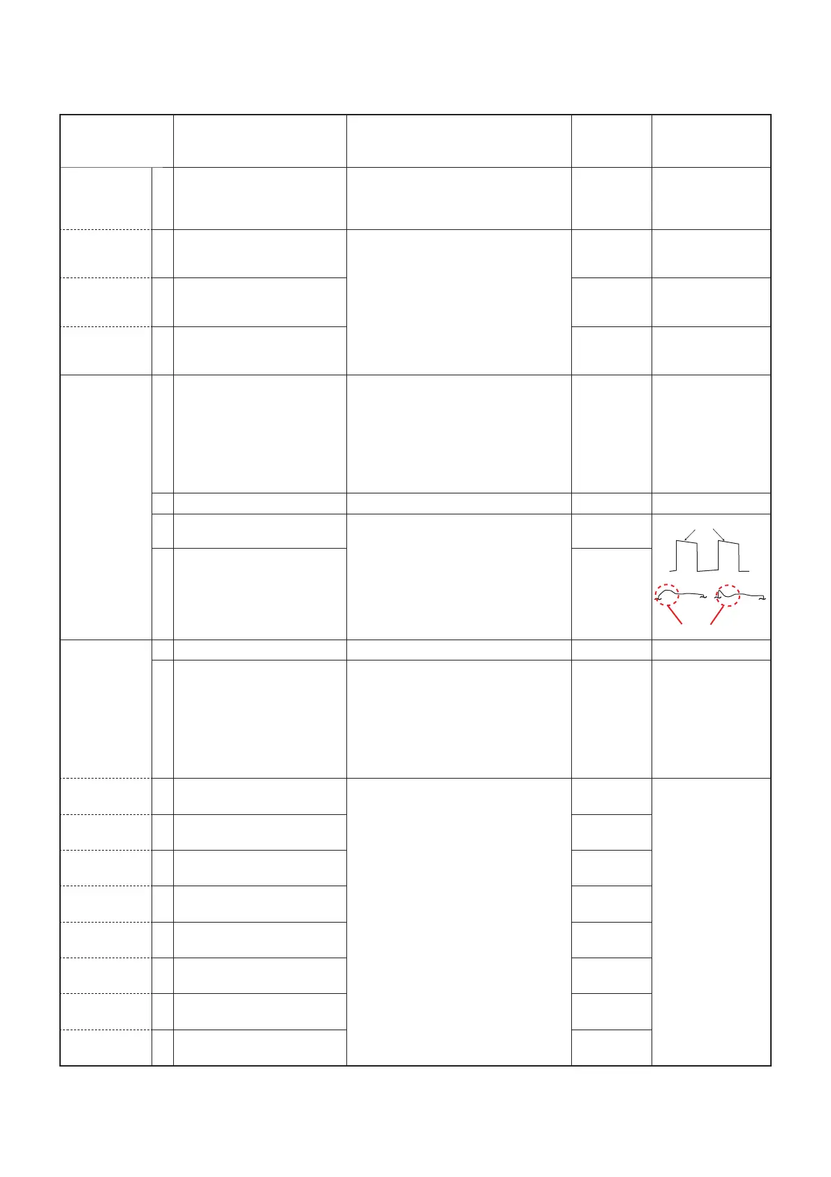
2) Observe the waveform on the oscil-
loscope.
[BAL]
4 • Channel: 1-14
• Transmitting
[BAL Offset
(High]
DIGITAL
DEVIATION
-Preparation-
1 – • Set the item [TX Mode] to "16." [TX Mode]
"16"
2
–
1) Connect the modulation analyzer to
the TX antenna connector through
the attenuator.
2) Set the modulation analyzer set to:
HPF: OFF
LPF: 20 kHz
De-emphasis: OFF
Detector: (P-P)/2
––
-Adjust-
(Band 1)
3 • Channel: 1-15
• Transmitting
1) Adjust the deviation using [
] / [
]
keys of the PC’s keyboard.
2) Push the [ENTER] key to store the
adjust value.
[MOD
(Digital)]
±1.37 ±0.02 kHz
(Band 2) 4 • Channel: 1-16
• Transmitting
[MOD Slant
Band 0]
(Band 3) 5 • Channel: 1-17
• Transmitting
[MOD Slant
Band 1]
(Band 4) 6 • Channel: 1-18
• Transmitting
[MOD Slant
Band 2]
(Band 5) 7 • Channel: 1-19
• Transmitting
[MOD Offset
(High)]
(Band 6) 8 • Channel: 1-20
• Transmitting
[MOD Slant
Band 3]
(Band 7) 9 • Channel: 1-21
• Transmitting
[MOD Slant
Band 4]
(Band 8) 10 • Channel: 1-22
• Transmitting
[MOD Slant
Band 5]
*: For IC-FR5100H.
6-9
No over or under shoot.
As flat as possible.

 Loading...


